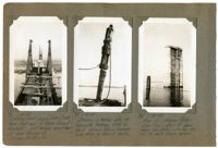
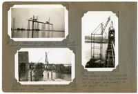
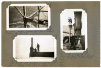
Image #71 (4.5" x 2.75"): "1-30-29. Looking west across Town Creek from west end of Drum Island Viaduct. Just before erection of Span Traveler B. Trusses 24 ft. c. to c."; Image #74 (4.5" x 2.75"): "1-30-29. Driving a batter pile for falsework footings with a No. 2 Vulcan steam hammer hung from a derrick boom."; Image #75 (4.5" x 2.75"): "1-30-29. Pier 12, Cooper River. Elev. top = 50.1 ft. above mean low water. Carries the 270 ft. deck truss spans.";Three 4.5" x 2.75" B/W photos numbered 71, 74, 75
Image #76 (2.75" x 4.5"): Temporary top chord links between U13 and U14, carrying diaphragms for hydraulic jacks - Town Creek Span."; Image #77 (2.75" x 4.5"): "End view of links shown in #76."; Image #78 (2.75" x 4.5): "End view of top chords U12 U13 at U13. (see #87).";Three 4.5" x 2.75" B/W photos numbered 76, 77, 78
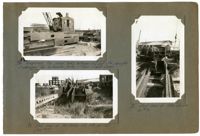
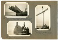
Image #79 (2.75" x 4.5"): "150 HP Gasoline hoisting engine (#5 or #6). Weight 31 tons."; Image #80 (2.75" x 4.5"): "100 HP Gasoline hoisting engine (#7). Weight about 26 tons."; Image #81 (2.75" x 4.5"): "Progress 2-1-29."; Image #82 (2.75" x 4.5"): "2-7-29. West cantilever completed to L12. Traveler at L10. Town Creek.";Four 4.5" x 2.75" B/W photos numbered 79, 80, 81, 82
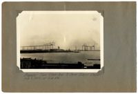
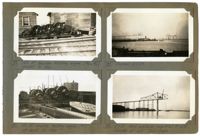
Image #83 (2.75" x 4.5"): "2-7-29. Material Tower erecting Span Traveler B. Viaduct traveler erecting Span 5D - Drum Island Viaduct."; Image #84 (2.75" x 4.5"): "2-7-29. Falsework footings Nos. 4 and 5, east anchor arm - Town Creek."; Image #85 (4.5" x 2.75"): "2-7-29. Steel material Tower F067 & F0187. 40 ft. square x 130 ft. high to boom heels. Two 70 ft. boom (30 ton capacity). On dock opposite Pier 4";Three 4.5" x 2.75" B/W photos numbered 83, 84, 85
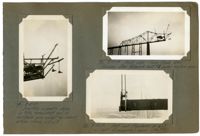
Image #87 (2.75" x 4.5"): "2-7-29. Top chords U12 U13 showing joint at U13 and temporary jacking links. Note eye bar hangers."; Image #88 (2.75" x 4.5"): "2-13-29. Bottom chord joint L13 - Town Creek. End joint of suspended span."; Image #89 (4.5" x 2.75"): "2-13-29. Assembly of top chord U12 U13, hanger, U13 L13 and joint L13 at end of suspended span.";Three 4.5" x 2.75" B/W photos numbered 87, 88, 89
Image #90 (4.5" x 2.75"): "2-13-29. Erecting assembly shown in #89, completing end of cantilever arm except for dummy bottom chords L12 L13."; Image #91 (2.75" x 4.5"): "2-13-29. West side - Town Creek Span. Removing steel falsework bent #1 under anchor arm."; Image #92 (2.75" x 4.5"): "2-14-29. Joint and floorbeam at L13 ( = Lo joint of suspended span. See #93).";Three 4.5" x 2.75" B/W photos numbered 90, 91, 92
Image #86 (2.75" x 4.5"): "Detail at boom heel - top of material tower. (See also #67)."; Image #93 (2.75" x 4.5"): "2-14-29. End floorbeam of suspended span erected before last (dummy) bottom chord of cantilever arm is in place."; Image #94 (2.75" x 4.5"): "2-14-29. Detail at front corner of Span Traveler, showing screw bearing jack and tie-down-rods.";Three 4.5" x 2.75" B/W photos numbered 96, 93, 94