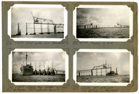
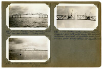
Image #323 (2.75" x 4.5"): "5-17-29. East anchor arm. Traveler at L6."; Image #324 (2.75" x 4.5"): "5-17-29. Progress in A.M."; Image #325 (2.75" x 4.5"): "5-18-29. Supply ship "Dobbin" and five Navy destroyers. West anchor arm beyond."; Image #329 (2.75" x 4.5"): "5-18-29. West anchor arm. Navy destroyer in foreground.";Four 4.5" x 2.75" B/W photos numbered 323, 324, 325, 329
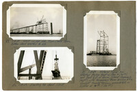
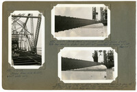
Image #49 (2.75" x 4.5"): "1-18-29. West anchor arm, Town Creek Span. Bottom chord erected to L6."; Image #50 (2.75" x 4.5"): "1-18-29. Erecting top chord U3U5."; Image #51 (4.5" x 2.75"): "1-18-29. Material Tower has erected Anchor Bent on Pier 4 (left), and Bent 1 D of Drum Island Approach (right) with temporary tower bracing b't'n. viaduct traveler trusses, assembled, on lighter at left. (See 57)";Three 4.5" x 2.75" B/W photos numbered 49, 50, 51
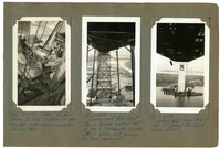
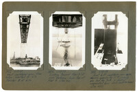
Image #108 (4.5" x 2.75"): "2-22-29. Detail of lead sheave at heel of boom on span traveler. Note swivel connection (See also #133)."; Image #110 (4.5" x 2.75"): "2-22-29. Looking west from top of Pier 2, toward anchored bent on Pier 1. Falsework columns still in place, but bracing has been removed."; Image #111. (4.5" x 2.75"): "2-22-29. Looking east from top of Pier 2 toward Pier 3 and Drum Island.";Three 4.5" x 2.75" B/W photos numbered 108, 110, 111
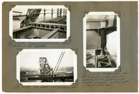
Image #120 (2.75" x 4.5"): "2-24-29. Expansion joint at L0. Plates supported on pipe separators."; Image #128 (2.75" x 4.5"): "3-3-29. Top chord - west cantilever arm."; Image #121 (4.5" x 2.75"): "2-24-29. Rocker shoe under end of viaduct girder, providing expansion between anchor arm and viaduct. Supported on cross girder at top of anchor bent.";Three 4.5" x 2.75" B/W photos numbered 120, 121, 128
Image #481 (4.5" x 2.75"): "6-22-29. Stairs from L16 to U17, east side only."; Image #482 (2.75" x 4.5"): "6-22-29. Closing chord L19 L21 east with pin driven at L21. Note how chord is arched and still not connected to hanger at L20. (Gap = 6")."; Image #483 (2.75" x 4.5"): "6-24-29. Same as above, after jacking near side down 6 1/8" and far side up 11 13/16", making total vertical movement at pin of 17 15/16". Note hanger being connected - chord is now straight.";Three 4.5" x 2.75" B/W photos numbered 481, 482, 483
Image #477 (2.75" x 4.5"): "6-21-29. U22 L22 = CL [center line] of span. Closing bottom chord, north truss, in place."; Image #478 (2.75" x 4.5"): "6-21-29. Progress."; Image #479 (2.75" x 4.5"): "6-22-29. Driving pin in L21 - East (See 476). This pin was later removed so that no shear could be transferred between the two cantilevers."; Image #480 (2.75" x 4.5"): "6-22-29. Both closing bottom chords in place, and pins driven, but not yet connected to hangers. See 482.";Four 4.5" x 2.75" B/W photos numbered 477, 478, 479, 480
Image #484 (2.75" x 4.5"): "6-25-29. Progress. Last verticals, U21 L21, east, have been erected. (Looking north)."; Image #485 (2.75" x 4.5"): "6-27-29. (Looking south). Showing complete suspended span (note portal bracing b'tn. end posts) cantilevered from ends of cantilever arms (which also have portal bracing between last diagonals L16 U17)."; Image #486 (2.75" x 4.5"): "6-27-29. Progress. All truss members in place.";Three 4.5" x 2.75" B/W photos numbered 484, 485, 486
Image #433 (4.5" x 2.75"): "6-13-29. West cantilever arm, from below, erected to L17. Traveler B at L16."; Image #434 (4.5" x 2.75"): "6-13-29. Looking toward Pier 8 (at 1050' distance) from top of Pier 9. (See 431)."; Image #435 (4.5" x 2.75"): "6-13-29. Joint L17, cantilever arm side, showing opening for 10" [diameter] jacking pin and for jack, to control suspended span while cantilevered. (See 488).";Three 4.5" x 2.75" B/W photos numbered 433, 434, 435