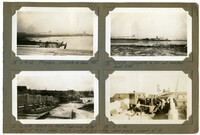
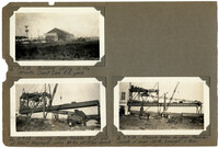
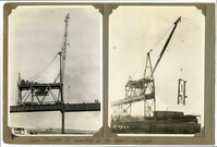
Image #14 (2.75" x 4.5"): "12-4-28. Progress. Complete to span 9W."; Image #19 (2.75" x 4.5"): "12-13-29. Complete to 5W and erecting bent 3W."; Images #17, 18 (2.75" x 4.5"): "12-8-28. Wreck on West Approach after runaway of 14 ton girder which pushed locomotive down grade ahead of it.";Four 4.5" x 2.75" B/W photos numbered 14, 17, 18, 19
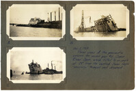
Images #8, 10, 12 (2.75" x 4.5"): Caption under all photos: Dec. 2, 1928. Three views of pneumatic caisson for anchor pier #10, Cooper River Span, which tilted to an angle 29 [degrees] from the vertical. Seven negro 'sand-hogs' trapped and drowned.";Three 4.5" x 2.75" B/W photos numbered 8, 10, 12
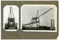
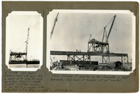
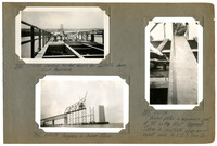
Image #5 (4.5" x 2.75"): "11-15-28. Front view of Span Traveler on the Charleston Approach."; Unnumbered Image (5" x 7"): "Erecting steel viaduct bent at 97 ft. reach.";One 4.5" x 2.75" B/W photo and one 5" x 7" B/W photo. Smaller photo numbered 5
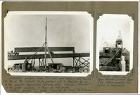
Unnumbered Image (5" x 7"): "Unloading girders from R.R. cars and loading onto trucks on top of viaduct, to be pushed out to traveler by an 8 ton gasoline locomotive (extreme left.) Max-load handled = 97 ft. girder weighing 16 tons up 6% grade. Stiffleg derrick S.O. H383 - Capacity 30 tons. 70 ft. boom."; Image #6 (4.5" x 2.75"): "11-15-28. Rear view of Span Traveler on West Appr. 8 ton Vulcan gasoline locomotive in foreground.";One 4.5" x 2.75" B/W photo and one 5" x 7" B/W photo. Smaller photo numbered 6.
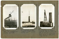
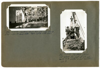
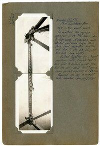
Image #1 (2.75" x 4.5"): "11-9-28. Building office in the Atlantic Coast Line R.R. Yard."; Image #2 (2.75" x 4.5"): "11-9-28. Erecting Span Traveler 'A' at and of West Approach, using 30 ton stiffleg derrick."; Image #3 (2.75" x 4.5"): "11-9-28. Raising boom for Span Traveler. Length of boom 100ft., & weight, 11 tons.";Three 4.5" x 2.75" B/W photos numbered 1, 2, 3
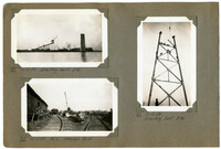
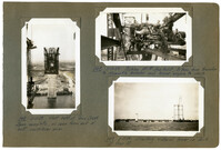
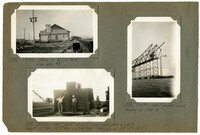
Image #13 (4.5" x 2.75"): "12-3-28. Span 10 W completed and erecting bent 8 W."; Image #15 (4.5" x 2.75"): "Charleston Viaduct completed to span 10 W. Looking west. 12-3-28."; Image #16 (4.5" x 2.75"): "12-3-28 Driving piles for false work footings under the west anchor arm of the Town Creek Span. Anchor Pier #1 in foreground. Main Pier #2 in background, elev. 134 ft.";Three 4.5" x 2.75" B/W photos numbered 13, 15, 16
Image #4 (4.5" x 2.75"): "11-15-28. High Boom! Minimum reach with main falls is about 5 ft. Note the slack backstays. Weight of traveler complete = 122 tons, including 31 ton; 150 HP gas. engine on the upper deck and 60 HP aux. gas hoist on platform below."; Unnumbered Image (5" x 7"): "Span traveler A erecting on the Charleston or West Approach. Rear boom of traveler not yet erected.";One 4.5" x 2.75" B/W photo and one 5" x 7" B/W photo. Smaller photo numbered 4.
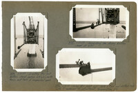
Image #147 (4.5" x 2.75"): "3-11-29. West half of Town Creek Span complete, as seen from end of east cantilever arm."; Image #148 (2.75" x 4.5"): "3-11-29. Picking 150 HP Gas. Hoist, 31 tons, from traveler to dismantle traveler and lower engine to deck."; Image #149 (2.75" x 4.5"): "3-11-29. Erecting material tower on dock at Pier 13.";Three 4.5" x 2.75" B/W photos numbered 147, 148, 149
Image #474 (4.5" x 2.75"): "6-21-29. Erecting the last bottom chord section L19' L21', north truss, east half of suspended span."; Image #475 (2.75" x 4.5"): "6-21-29. Connecting the closing bottom chord at L21'."; Image #476 (2.75" x 4.5"): "6-21-29. Closing B.C. joint L21'. Note 6" [diameter] pin and slotted hole with 7" movement for adjustment, temperature, etc.";Three 4.5" x 2.75" B/W photos numbered 474, 475, 476
Image #471 (2.75" x 4.5"): "Progress. Ready to place the last 87 1/6" bottom chord section."; Image #472 (2.75" x 4.5"): "6-21-29. Ready for the last or closing bottom chord sections."; Image #473 (4.5" x 2.75"): "6-21-29. From below. West cantilever, below. East cantilever, above.";Three 4.5" x 2.75" B/W photos numbered 471, 472, 473
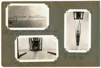
Image #320 (2.75" x 4.5"): "5-17-29. Setting timber forms for concrete deck, East Approach."; Image #321 (4.5" x 2.75"); "5-17-29. Bowed plates in expansion joint at 9E on the East Approach. Taken to illustrate shop error. report made to V.B. & Iron Co."; Image #322 (2.75" x 4.5"): "5-17-29. Progress in Cooper River.";Three 4.5" X 2.75" B/W photos numbered 320, 321, 322
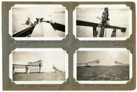
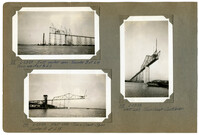
Image #372 (2.75" x 4.5"): "5-29-29. Looking down from U10, over Pier 8. Elev. = 280 ft. above water. Note lighter with steel."; Image #373 (4.5" x 2.75"): "5-29-29. Top chord U8 U10 just entered into joint at U8 and ready to be pulled in and connected. Span 9.";Two 4.5" x 2.75" B/W photos numbered 372, 373
Image #399 (2.75" x 4.5") and Image #400 (2.75" x 4.5"): "Member U12 L12 East Cantilever Arm. 96'-0" c. to c. panel points. As erected this member appeared to be 3 1/2" short, due to fabrication of members, some shorter and some longer than their final geometric lengths, and due to the sub-diagonal M11 L12 (lower right). Pulled together by a 7-part auxiliary falls. Engine kept in high gear to reduce power - max. lead line pull = about 9000 [pounds], approx., giving possible capacity of 130 tons. Required one day to connect each member - two days total.;Two 4.5" x 2.75" B/W photos numbered 399, 400
Image #336 (2.75" x 4.5"): "5-18-29. Office in A.C.L. Yard. See also #1."; Image #337 (2.75" x 4.5"): "Bottom chord joint at L10 - over main piers 8 and 9. Weight 13 tons. 12'-7" long x 12'-4" high (Main gas. pl. 108" x 1" x 12'-7")."; Image #338 (4.5" x 2.75"): "5-21-29. West anchor arm landing on Pier 8.";Three 4.5" x 2.75" B/W photos numbered 336, 337, 338
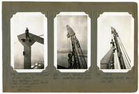
Image #113 (2.75" x 4.5"): "2-23-29. East anchor arm. Traveler Bat L4 Truss erected to L6."; Image #114 (2.75" x 4.5"): "2-23-29. West side - Town Creek Span. Traveler A at L15."; Image #115 (4.5" x 2.75"): "2-23-29. West side - Town Creek Cantilever.";Three 4.5" x 2.75" B/W photos numbered 113, 114, 115