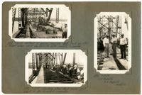
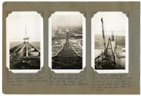
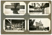
Image #534 (2.75" x 4.5"): "7-13-29. Method of pouring concrete deck. Track elevated on timber horses which are removed after concrete is poured."; Image #535 (2.75" x 4.5"): "7-13-29. Riveting steel deck beams - just ahead of the formwork carpenters."; Image #536 (4.5" x 2.75"): "7-13-29. J.H. Reynolds. W.E. Reynolds. Winston.";Three 4.5" x 2.75" B/W photos numbered 534, 535, 536
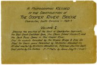
A Photographic Record of the Construction of the Cooper River Bridge; Charleston, South Carolina - 1928-29; Volume I; Showing the erection of the West or Charleston approach, the Town Creek Cantilever Span, the Drum Island Viaduct, and the Deck Truss Spans in the Cooper River. Steel for viaducts furnished by the Virginia Bridge & Iron Co. Steel for truss spans furnished by McClintic-Marshall Co. All steel erected by McClintic-Marshall Co., Pottstown Erection Dep't. Small photos by E.L. Durkee. 5" x 7" Photos by James Smyth ("Irish").;Title Page, 6.75" x 10.125"
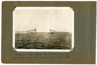
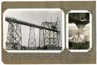
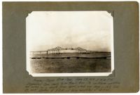
Unnumbered Image (5" x 7'): "Progress in Cooper River, May 31, 1929 at 4:30 P.M. Lost 3 days since May 24 on account of lack of steel.";One 5" x 7" B/W photo
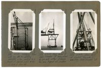
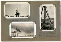
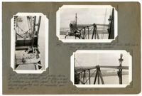
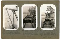
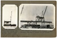
Image #235 (4.5" x 2.75"): "4-7-29. Material Tower with two 50 ton stiffleg derricks on top, erected to a height of 3 panels (ab't 95 ft.) On dock at Pier 13."; Image #238 (4.5" x 2.75"): "4-9-29. Main boom of Span Traveler 'B' being raised by gin pole after A-frame has been tripped into position."; Image #239 (4.5" x 2.75"): "4-9-29. From deck of Viaduct Traveler 'C', erecting Span Traveler 'B'.";Three 4.5" x 2.75" B/W photos numbered 235, 238, 239
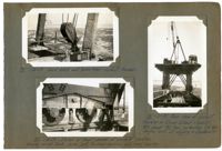
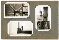
Image #70 (2.75" x 4.5"): " 1-30-29. Lead block and boom heel - viaduct traveler."; Image #72 (2.75" x 4.5"): "1-30-29. Detail at front corner of viaduct traveler, showing swivel truck, 40 ton jack, tie-down anchors, and front bearing."; Image #73 (4.5" x 2.5"): "1-30-29. rear view of viaduct traveler on Drum Island Viaduct. Wt. about 80 tons, including 25 ton engine and all rigging & counterw't.";Three 4.5" x 2.75" B/W photos numbered 70, 72, 73
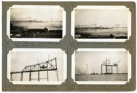
Image #61 (2.75" x 4.5"): "1-23-29. Progress - Town Creek Span. Taken from office tower."; Image #62 (2.75" x 4.5"): "Progress - Town Creek & Drum Island (right). 1-26-29."; Image #63 (2.75" x 4.5"):"1-28-29. West anchor arm complete."; Image #64 (2.75" x 4.5"): "1-28-29. Viaduct traveler starting erection of Drum Island Viaduct. span traveler not yet erected.";Four 4.5" x 2.75" B/W photos numbered 61, 62, 63, 64
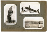
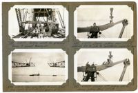
Image #236 (2.75" x 4.5"): "4-7-29. Rear view of Viaduct Traveler 'C' erecting Span Traveler 'A' on Span 5."; Image #237 (2.75" x 4.5"): "4-7-29. Side view of #236."; Image #232 (4.5" x 2.75"): "4-7-29. Top deck of double-deck Span Traveler A, looking toward rear boom, A-frame and backstay connection.";Three 4.5" x 2.75" B/W photos numbered 232, 236, 237
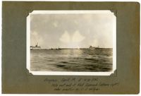
Unnumbered Image (5" x 7"): "Progress, April 19, 1929 at 4:30 P.M. Note east end of East Approach (extreme right) under erection by C.E. Hillyer.";One 5" x 7" B/W photo
Unnumbered Image (5" x 7"): "1-28-29. West Anchor arm of the Town Creek Span and east end of the Charleston Approach Viaduct. Anchor arm is 256 ft. long (8 panels at 32 ft.). Stair tower at left."; Image #66 (4.5" x 2.75"): "1-30-29. Main bearing shoe, Pier 2, Town Creek Span. 5' 0" x 5' 9" = 28.75 [square feet]. Des. Load = 1,813,000# = 438 # [per square inch]. Erec. Load = 1,089,000# max. (suspended span cantilevered to center). Lower shoe 3' 4" high.";One 4.5" x 2.75" B/W photo and one 5" x 7" B/W photo. Smaller photo numbered 66.
Image #451 (4.5" x 2.75"): "6-18-29. Bow in main compression diagonal L14 U15, south truss, east cantilever arm. Measured deflection 1 9/16". Note string at lower left. See 495 and 496 for method of straightening."; Image #553 (4.5" x 2.75"): "7-27-29. L14 U15 after being straightened while under load in the bridge. Note straight string along lower left flange. Max variation is now 7/16" at lower end only. Remainder straight."; Image #452 (4.5" x 2.75"): "6-19-29. West cantilever (far side) to L21 and east arm (top) to L17 with hangers at U18 L18.";Three 4.5" x 2.75" B/W photos numbered 451, 453, 553
Image #488 (4.5" x 2.75"): "6-27-29. Bottom chord jacking device at L17. 500-Ton hydraulic jack in place in end of cantilever arm bottom chord. Note eye-bar hangers supporting end of suspended span thru 10" [diameter] pin."; Image #492 (2.75" x 4.5"): "6-27-29. Entering closing top chord at U22. Note gap in truss at left for closing member."; Image #493 (2.75" x 4.5"): "6-27-29. Same as 492.";Three 4.5" x 2.75" B/W photos numbered 488, 492, 493
Image #382 (2.75" x 4.5"): "5-31-29. Erecting peak strut at U10 west side, by hauling it around in the back of the boom. Traveler at L10."; Image #383 (4.5" x 2.75"): "5-31-29. Final position of 382. Erecting strut in this manner took about 2 hours as compared with 10 minutes for method shown in 379."; Image #384 (2.75" x 4.5"): "5-31-29. Looking west from U10 on east side.";Three 4.5" x 2.75" B/W photos numbered 382, 383, 384
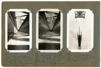
Image #95 (2.75" x 4.5"): "2-15-29. Looking down Drum Island Viaduct toward Cooper River. Viaduct Traveler C erecting."; Image #98 (2.75" x 4.5"): "2-22-29. From the peak of the Town Creek Span (U8), elev. 235 ft. looking west down the Charleston Approach."; Image #99 (2.75" x 4.5"): "2-22-29. Looking east from U8, toward Drum Island Traveler at L13, rear boom in foreground. Main boom, boomed out flat, can be seen thru the A-frame.";Three 4.5" x 2.75" B/W photos numbered 95, 98, 99
Image #86 (2.75" x 4.5"): "Detail at boom heel - top of material tower. (See also #67)."; Image #93 (2.75" x 4.5"): "2-14-29. End floorbeam of suspended span erected before last (dummy) bottom chord of cantilever arm is in place."; Image #94 (2.75" x 4.5"): "2-14-29. Detail at front corner of Span Traveler, showing screw bearing jack and tie-down-rods.";Three 4.5" x 2.75" B/W photos numbered 96, 93, 94
Image #457 (4.5" x 2.75"): "6-19-29. Eye-bar hangers U17 L17 at end of cantilever arm, supporting the suspended span."; Image #458 (4.5" x 2.75"): "6-19-29. Jacking diaphragm for 500 ton hydraulic jack in dummy chord U17 U18. Pin carryin [sic] eye-bar hangers is just beyond."; Image #459 (4.5" x 2.75"): "6-19-29. 500-Ton hydraulic jack in place and connected with pump. Saddle casting (foreground) bears on 10" [diameter] jacking pin shown in 456. Drake - Varga.";Three 4.5" x 2.75" B/W photos numbered 457, 458, 459
Image #453 (2.75" x 4.5"): "6-20-29. Jacking stick for spreading trusses to connect bracing, etc."; Image #454 (2.75" x 4.5"): "6-19-29. West arm (left) to L21. East arm (right) to L17 U18. (CL [center line] of span is at 22)."; Image #455 (2.75" x 4.5"): "6-19-29. Dummy jacking chord U17 U18 containing 500 ton jack for cantilevering suspended span."; Image #456 (2.75" x 4.5"): "6-19-29. Driving 10" [diameter] jacking pin in dummy jacking chord U17 U18.";Four 4.5" x 2.75" B/W photos numbered 453, 454, 455, 456
Unnumbered Image (5" x 7"): "Progress - Cooper River Span, June 28, 1929 at 4:30 P.M. Suspended span ready to be freed from its cantilever condition and swung as a simple truss span, which was done on Sat., June 29, 1929, starting at 8 A.M. and being completed at 3: P.M.";One 5" x 7" B/W photo
Image #181 (2.75" x 4.5"): "3-20-29. Detail of shoe at top of falsework bent under deck span."; Image #182 (2.75" x 4.5"): "3-17-29. Fuel oil compressor - (semi-diesel)."; Image #201 (2.75" x 4.5"): "4-1-29. End View of #181."; Image #183 (2.75" x 4.5"): "3-20-29. Twist in 40 ft. viaduct girder due to improper loading for shipment.";Four 4.5" x 2.75" B/W photos numbered 181, 182, 183, 201
Image #4 (4.5" x 2.75"): "11-15-28. High Boom! Minimum reach with main falls is about 5 ft. Note the slack backstays. Weight of traveler complete = 122 tons, including 31 ton; 150 HP gas. engine on the upper deck and 60 HP aux. gas hoist on platform below."; Unnumbered Image (5" x 7"): "Span traveler A erecting on the Charleston or West Approach. Rear boom of traveler not yet erected.";One 4.5" x 2.75" B/W photo and one 5" x 7" B/W photo. Smaller photo numbered 4.