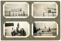
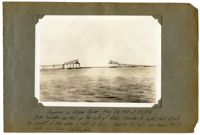
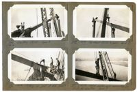
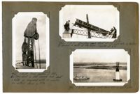
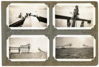
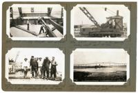
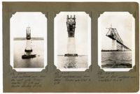
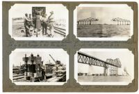
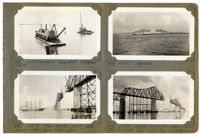
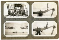
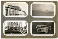
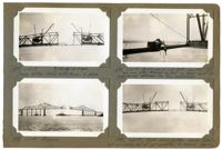
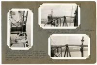
Image #339 (2.75" x 4.5"): "5-21-29. West anchor arm ready to erect last panel 8-10, and land on main pier 8."; Image #340 (2.75" x 4.5"): "5-22-29. East anchor arm erecting last panel 8-10, to land on main pier 9."; Image #341 (2.75" x 4.5"): "5-22-29. Setting shoe in Pier 8. wt. of lower shoe = 10 tons. Base 7'-3 x 8'-6 = 61.6 [square feet]"; Image #342 (2.75" x 4.5"): "5-22-29. Setting main shoes on Pier 8.";Four 4.5" x 2.75" B/W photos numbered 339, 340, 341, 342
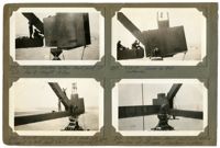
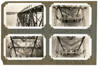
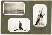
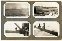
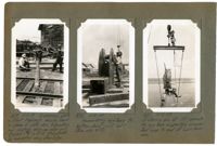
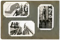
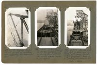
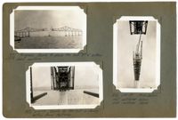
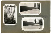
Image #343 (2.75" x 4.5"): "5-22-29. Erecting bottom chord joint at L10, Pier 8. Weight 13 tons."; Image #344 (2.75" x 4.5"): "5-22-29. Same as 343. (Leatherman)."; Image #345 (2.75" x 4.5"): "5-22-29. Pulling joint L10 back into place to connect to bott. chord L8 L10 and diagonal M9 L10."; Image #348 (2.75" x 4.5"): "5-23-29. Bottom chord joint L10 before erection of stringers. Floorbeam in place.";Four 4.5" x 2.75" B/W photos numbered 343, 344, 345, 348
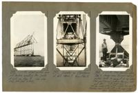
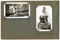
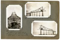
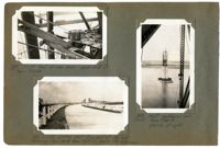
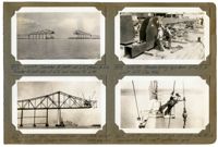
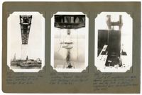
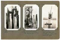
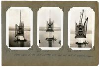
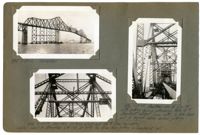
Image #346 (4.5" x 2.75"): " 5-22-29. East anchor arm just before erecting the joints at L10 on Pier 8. (See also 343, 344, 345, & 348)."; Image #347 (4.5" x 2.75"): "Traveler on floorbeam at L8, Span 7, from Pier 8."; Image #349 (4.5" x 2.75"): "5-23-29. Main bearing shoe, Pier 9. Anchor arm trusses not yet pulled back to connect to top shoe. See pulling and jacking devices, 350 and 351. 7'-3 x 8'-6 = 61.6 [square feet]. Max. Des. Load = 3,916,000 [pounds] = 63,540 [pounds/square feet] = 440 [pounds/square inch]. Max. Erec. Load = 2,658,000 [pounds] with suspended span cantilevered to center.";Three 4.5" x 2.75" B/W photos numbered 346, 347, 349
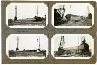
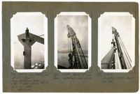
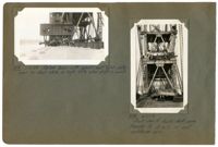
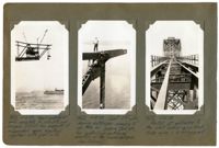
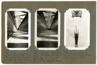
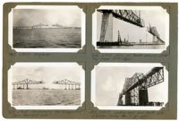
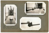
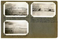
Image #350 (2.75" x 4.5"): "5-23-29. Pulling device (at left) at L0 - Span 9. Where deck span adjoins anchor arm."; Image #351 (2.75" x 4.5"): "5-23-29. Jacking device at end of anchor arm. Pulling device, showing turnbuckle - just beyond."; Image #352 (2.75" x 4.5"): "5-23-29. West anchor arm landed on Pier 8 (right)."; Image #353 (2.75" x 4.5"): "5-24-29. Looking west from Span 9.";Four 4.5" x 2.75" B/W photos numbered 350, 351, 352, 353
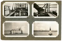
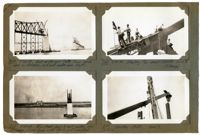
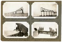
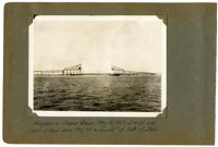
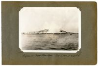
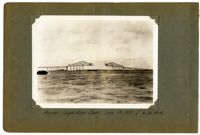
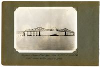
Unnumbered Image (5" x 7"): "Progress in Cooper River, May 24, 1929 at 5: P.M. Both travelers are tied up for lack of steel. Traveler A (right) held at L8 on account of shop error in joint at L10. Traveler B (left) has moved to L9. Note U.S. Navy destroyers.";One 5" x 7" B/W photo
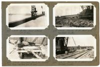
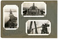
Image #354 (2.75" x 4.5"): "5-26-29. Deck spans 10, 11, and 12 - from stair tower at Pier 10. Trusses are 40 ft. deep."; Image #355 (2.75" x 4.5"): "5-26-29. Looking down from deck of bridge at falsework footing #31, under L8. Span 9. (See 333)."; Image #356 (2.75" x 4.5"): "5-26-29. Same as 355."; Image # 5-26-29. Falsework footing #32, under L6, Span 9. (See also 334).";Four 4.5" x 2.75" B/W photos numbered 354, 355, 356, 357
Image #360 (2.75" x 4.5"): "5-28-29. rolling top chord U8 U10 - 100 ft. long Wt. 36 tons."; Image #361 (2.75" x 4.5"): "5-28-29. U8 U10 being rolled right side up for erection. Note special rolling slings & sheaves."; Image #362 (2.75" x 4.5"): "5-28-29. Loading U8 U10 on truck to be run out and loaded on lighter."; Image #363 (2.75" x 4.5"): "5-28-29. Loading U8 U10 on lighter.";Four 4.5" x 2.75" B/W photos numbered 360, 361, 362, 363
Image #364 (2.75" x 4.5"): "5-28-29. East anchor arm (left) - Town Creek Span in distance and west anchor arm (right)."; Image #365 (2.75" x 4.5"): "5-29-29. Town Creek Span & west anchor arm of Cooper River Span with U8 U10 just erected."; Image #366 (2.75" x 4.5"): "5-29-29. Erecting top chord U8 U10. Span 9. (Patterson)."; Image #367 (2.75" x 4.5"): "5-29-29. Erecting U8 U10. Span 9.";Four 4.5" X 2.75" B/W photos numbered 364, 365, 366, 367
Image #372 (2.75" x 4.5"): "5-29-29. Looking down from U10, over Pier 8. Elev. = 280 ft. above water. Note lighter with steel."; Image #373 (4.5" x 2.75"): "5-29-29. Top chord U8 U10 just entered into joint at U8 and ready to be pulled in and connected. Span 9.";Two 4.5" x 2.75" B/W photos numbered 372, 373
Image #377 (2.75" x 4.5"): "5-29-29. West side. First truss members erected in cantilever arm."; Image #378 (2.75" x 4.5"): "5-29-29. East anchor arm complete. Traveler at L9."; Image #379 (2.75" x 4.5"): "5-31-29. Traveler at L9 erecting peak strut at U10. Then moves back 15 ft. to allow boom to "duck" under strut and move forward.. Not drift."; Image #380 (2.75" x 4.5"): "5-31-29. Peak strut at U10 east side, as shown in 379.";Four 4.5" x 2.75" B/W photos numbered 377, 378, 379, 380
Image #382 (2.75" x 4.5"): "5-31-29. Erecting peak strut at U10 west side, by hauling it around in the back of the boom. Traveler at L10."; Image #383 (4.5" x 2.75"): "5-31-29. Final position of 382. Erecting strut in this manner took about 2 hours as compared with 10 minutes for method shown in 379."; Image #384 (2.75" x 4.5"): "5-31-29. Looking west from U10 on east side.";Three 4.5" x 2.75" B/W photos numbered 382, 383, 384
Unnumbered Image (5" x 7'): "Progress in Cooper River, May 31, 1929 at 4:30 P.M. Lost 3 days since May 24 on account of lack of steel.";One 5" x 7" B/W photo
Image #381 (4.5" x 2.75"): "5-31-29. Top chord of east anchor arm, as seen from U1. Peak strut at U10 (top) is highest point of span - elev. 280 ft."; Image #385 (2.75" x 4.5"): "6-1-29. West side - erecting cantilever arm."; Image #386 (2.75" x 4.5"): "6-1-29. Erecting cantilever arm - east side.";Three 4.5" x 2.75" B/W photos numbered 381, 385, 386
Image #387 (2.75" x 4.5"): "Progress 6-1-29"; Image #388 (2.75" x 4.5"): "6-3-29. E.L.D. at U10, watching erection of top chord U10 U12, east side. (See 390 & 391)."; Image #389 (4.5" x 2.75"): "6-2-29. Starting erection of east cantilever arm.";Three 4.5" x 2.75" B/W photos numbered 387, 388, 389
Image #395 (2.75" x 4.5"): "6-6-29. Heel of main boom - upper deck of Span Traveler."; Image #398 (4.5" x 2.75"): "6-6-29. West cantilever arm, from Pier 9. U12 L12 at right."; Image #401 (2.75" x 4.5"): "6-6-29. Looking west from end of the east causeway. Town Creek Span (left) is nearly 1 3/4 miles away.";Three 4.5" x 2.75" B/W photos numbered 395, 398, 401
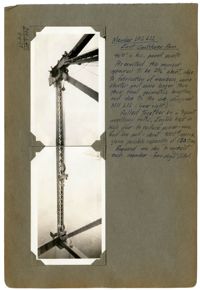
Image #399 (2.75" x 4.5") and Image #400 (2.75" x 4.5"): "Member U12 L12 East Cantilever Arm. 96'-0" c. to c. panel points. As erected this member appeared to be 3 1/2" short, due to fabrication of members, some shorter and some longer than their final geometric lengths, and due to the sub-diagonal M11 L12 (lower right). Pulled together by a 7-part auxiliary falls. Engine kept in high gear to reduce power - max. lead line pull = about 9000 [pounds], approx., giving possible capacity of 130 tons. Required one day to connect each member - two days total.;Two 4.5" x 2.75" B/W photos numbered 399, 400
Image #397 (4.5" x 2.75"): "6-6-29. Main boom - span Traveler. 100 ft. long c. to c. pins. Taken from near heel looking up towards tip at U12."; Image #403 (2.75" x 4.5"): "6-6-29. Setting reinforcing steel - east approach."; Image #404 (2.75" x 4.5"): "6-6-29. 4 Ton Gas. Locomotive & dump cars for pouring concrete deck, east approach & causeway.";Three 4.5" x 2.75" B/W photos numbered 397, 403, 404
Image #405 (2.75" x 4.5"): "6-7-29. Erecting stringers - east cantilever."; Image #406 (2.75" x 4.5"): "6-8-29. Crane 19. 40 Ton capacity. Working weight about 100 tons."; Image #407 (2.75" x 4.5"): "6-8-29. Dummies made up to throw off of top of span as practice drill for life savers."; Image #409 (2.75" x 4.5"): "6-8-29. Town Creek Span with advertising sign 13' x 30' in place at center.";Four 4.5" x 2.75" B/W photos numbered 405, 406, 407, 409
Image #414 (2.75" x 4.5"): "6-10-29. Balance beam with special bent hitch plates used for short hitch on high lifts wher [sic] drift is small."; Image #415 (4.5" x 2.75"): "6-11-29. Front view of double-deck span traveler A at L12 on east cantilever arm.";Two 4.5" x 2.75" B/W photos numbered 414, 415
Image #416 (4.5" x 2.75"): "6-11-29. East cantilever arm, from the west side. Trusses erected to L14 and traveler standing at L12."; Image #417 (4.5" x 2.75"): "6-11-29. East cantilever arm from below. Trusses are erected to L14."; Image #418 (4.5" x 2.75"): "6-11-29. View of East cantilever arm, completed to L14.";Three 4.5" x 2.75" B/W photos numbered 416, 417, 418
Image #419 (4.5" x 2.75"): "6-11-29. Expansion plate on East Approach showing bend in plane of plate due to punching and riveting along one edge only. Bowed 1 3/4" in 20 ft. Straightened by hammering along other edge."; Image #420 (4.5" x 2.75"): "6-12-29. Assembling eye-bars to bottom chord joint L17. (See also 424)."; Image #421 (4.5" x 2.75"): "6-12-29. Entering pin at U17 connecting eye-bars supporting suspended span to end of cantilever arm.";Three 4.5" x 2.75" B/W photos numbered 419, 420, 421
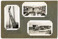
Image #422 (2.75" x 4.5"): "6-11-29. Traveler B (left) at L15 & truss to L16. Traveler A (east side) at L12 and truss to L14."; Image #423 (2.75" x 4.5"): "6-12-29. West cantilever arm complete except floor L16 to L17. Eye-bar hangers U17 L17 being erected."; Image #424 (2.75" x 4.5"): "6-12-29. Assembling eye-bars U17 L17 to joint L17 (See 420)."; Image #425 (2.75" x 4.5"): "6-12-29. Driving 10" pin at U17 with 500lb. overhauling ball - west cantilever arm.";Four 4.5" x 2.75" B/W photos numbered 422, 423, 424, 425
Image #426 (4.5" x 2.75"): "6-12-29. West cantilever arm complete to L16 U17 and hangers U17 L17 for support of suspended span erected, together with joint L17."; Image #427 (4.5" x 2.75"): "6-12-29. Joint U17 with dummy extension carrying 10" pin hole for jacking pin, etc., for controlling cantilever erection of the suspended span. (Geo. Schnell)."; Image #428 (4.5" x 2.75"): "6-12-29. Portal at entrance to the west anchor arm. Deck truss span 6 in foreground.";Three 4.5" x 2.75" B/W photos numbered 426, 427, 428
Image #429 (2.75" x 4.5"): "6-11-29. Lifting 500 ton capacity hydraulic jack by its 12 1/2" [diameter] plunger to test the section."; Image #430 (2.75" x 4.5"): "6-12-29. Frame for testing hydraulic jacks. Capacity about 50 tons."; Image #431 (2.75" x 4.5"): "6-13-29. Progress. West cantilever (left) complete to U17 L17. Right (east) arm to L16."; Image #432 (2.75" x 4.5"): "6-12-29. Looking east from south of Pier 5.";Four 4.5" x 2.75" B/W photos numbered 429, 430, 431, 432
Image #433 (4.5" x 2.75"): "6-13-29. West cantilever arm, from below, erected to L17. Traveler B at L16."; Image #434 (4.5" x 2.75"): "6-13-29. Looking toward Pier 8 (at 1050' distance) from top of Pier 9. (See 431)."; Image #435 (4.5" x 2.75"): "6-13-29. Joint L17, cantilever arm side, showing opening for 10" [diameter] jacking pin and for jack, to control suspended span while cantilevered. (See 488).";Three 4.5" x 2.75" B/W photos numbered 433, 434, 435
Image #437 (2.75" x 4.5"): "6-13-29. Bottom chord L14 L16. Wt. 17 tons."; Image #438 (2.75" x 4.5"): "6-14-29. Turntable truck for turning long truss members end for end."; Image #439 (2.75" x 4.5"): "6-14-29. Turning 90 ft. chord with turntable trucks."; Image #440 (2.75" x 4.5"): "6-14-29. Turning 90 ft. chord with turntable trucks.";Four 4.5" x 2.75" B/W photos numbered 437, 438, 439, 440
Image #411 (2.75" x 4.5"): "6-18-29. U.S. Engineers' Snag-boat 'Wateree.'"; Image #442 (2.75" x 4.5"): "6-18-29. Four-masted sailing ship passing under Cooper River Span."; Image #443 (2.75" x 4.5"): "6-17-29. Progress."; Image #444 (2.75" x 4.5"): "6-18-29. Looking west from Cooper River. Pier 10 at left. Town Creek Span in background.";Four 4.5" x 2.75" B/W photos numbered 441, 442, 443, 444
Image #445 (2.75" x 4.5"): "6-18-29. Joint L17 - end of suspended span. Note 3" [diameter] pin and slotted hole for expansion."; Image #446 (2.75" x 4.5"): "6-18-29. Pulling piles using Union No. 2 steam hammer, inverted, and taking a strain with 3-part falls by "Wateree"."; Image #447 (4.5" x 2.75"): "6-18-29. Ready to pull.";Three 4.5" x 2.75" B/W photos numbered 445, 446, 447
Image #448 (4.5" x 2.75"): "6-18-29. Pulling."; Image #449 (4.5" x 2.75"): "6-18-29. First pile pulled. Time required, about 15 min."; Image #450 (4.5" x 2.75"): "6-18-29. West cantilever arm. Traveler at L19 on the suspended span.";Three 4.5" x 2.75" B/W photos numbered 448, 449, 450
Image #451 (4.5" x 2.75"): "6-18-29. Bow in main compression diagonal L14 U15, south truss, east cantilever arm. Measured deflection 1 9/16". Note string at lower left. See 495 and 496 for method of straightening."; Image #553 (4.5" x 2.75"): "7-27-29. L14 U15 after being straightened while under load in the bridge. Note straight string along lower left flange. Max variation is now 7/16" at lower end only. Remainder straight."; Image #452 (4.5" x 2.75"): "6-19-29. West cantilever (far side) to L21 and east arm (top) to L17 with hangers at U18 L18.";Three 4.5" x 2.75" B/W photos numbered 451, 453, 553
Image #453 (2.75" x 4.5"): "6-20-29. Jacking stick for spreading trusses to connect bracing, etc."; Image #454 (2.75" x 4.5"): "6-19-29. West arm (left) to L21. East arm (right) to L17 U18. (CL [center line] of span is at 22)."; Image #455 (2.75" x 4.5"): "6-19-29. Dummy jacking chord U17 U18 containing 500 ton jack for cantilevering suspended span."; Image #456 (2.75" x 4.5"): "6-19-29. Driving 10" [diameter] jacking pin in dummy jacking chord U17 U18.";Four 4.5" x 2.75" B/W photos numbered 453, 454, 455, 456
Image #457 (4.5" x 2.75"): "6-19-29. Eye-bar hangers U17 L17 at end of cantilever arm, supporting the suspended span."; Image #458 (4.5" x 2.75"): "6-19-29. Jacking diaphragm for 500 ton hydraulic jack in dummy chord U17 U18. Pin carryin [sic] eye-bar hangers is just beyond."; Image #459 (4.5" x 2.75"): "6-19-29. 500-Ton hydraulic jack in place and connected with pump. Saddle casting (foreground) bears on 10" [diameter] jacking pin shown in 456. Drake - Varga.";Three 4.5" x 2.75" B/W photos numbered 457, 458, 459
Image #460 (4.5" x 2.75"): "6-19-29."; Image #461 (4.5" x 2.75"): "6-20-29."; Image #462 (4.5" x 2.75"): "6-20-29."; "Three views of the west cantilever arm and west half of suspended span.";Three 4.5" x 2.75" B/W photos numbered 460, 461, 462
Image #463 (2.75" x 4.5"): "6-19-29. Progress."; Image #464 (2.75" x 4.5"): "6-19-29. Cantilevering the suspended span from each side."; Image #465 (2.75" x 4.5"): "6-19-29. Navy oil tanker passing under the Cooper River Span."; Image #466 (2.75" x 4.5"): "6-20-29. Looking east from north side of bridge. Anchor Pier 7 at right.";Four 4.5" x 2.75" B/W photos numbered 463, 464, 465, 466
Image #467 (2.75" x 4.5"): "6-20-29. E.L.D.'s favorite view. See also Nos. 174, 364, 444, 494, 554, and 571."; Image #468 (2.75" x 4.5"): "6-20-29. Progress."; Image #469 (2.75" x 4.5"): "6-20-29. Deck of west cantilever arm. G.R. Bullard, H.J. Stetina."; Image #470 (2.75" x 4.5"): "6-21-29. Looking down on anchorage lighter for mooring other lighters. Four anchors controlled by steam hoist.";Four 4.5" x 2.75" B/W photos numbered 467, 468, 469, 470
Image #471 (2.75" x 4.5"): "Progress. Ready to place the last 87 1/6" bottom chord section."; Image #472 (2.75" x 4.5"): "6-21-29. Ready for the last or closing bottom chord sections."; Image #473 (4.5" x 2.75"): "6-21-29. From below. West cantilever, below. East cantilever, above.";Three 4.5" x 2.75" B/W photos numbered 471, 472, 473
Image #474 (4.5" x 2.75"): "6-21-29. Erecting the last bottom chord section L19' L21', north truss, east half of suspended span."; Image #475 (2.75" x 4.5"): "6-21-29. Connecting the closing bottom chord at L21'."; Image #476 (2.75" x 4.5"): "6-21-29. Closing B.C. joint L21'. Note 6" [diameter] pin and slotted hole with 7" movement for adjustment, temperature, etc.";Three 4.5" x 2.75" B/W photos numbered 474, 475, 476
Image #477 (2.75" x 4.5"): "6-21-29. U22 L22 = CL [center line] of span. Closing bottom chord, north truss, in place."; Image #478 (2.75" x 4.5"): "6-21-29. Progress."; Image #479 (2.75" x 4.5"): "6-22-29. Driving pin in L21 - East (See 476). This pin was later removed so that no shear could be transferred between the two cantilevers."; Image #480 (2.75" x 4.5"): "6-22-29. Both closing bottom chords in place, and pins driven, but not yet connected to hangers. See 482.";Four 4.5" x 2.75" B/W photos numbered 477, 478, 479, 480
Image #481 (4.5" x 2.75"): "6-22-29. Stairs from L16 to U17, east side only."; Image #482 (2.75" x 4.5"): "6-22-29. Closing chord L19 L21 east with pin driven at L21. Note how chord is arched and still not connected to hanger at L20. (Gap = 6")."; Image #483 (2.75" x 4.5"): "6-24-29. Same as above, after jacking near side down 6 1/8" and far side up 11 13/16", making total vertical movement at pin of 17 15/16". Note hanger being connected - chord is now straight.";Three 4.5" x 2.75" B/W photos numbered 481, 482, 483
Image #484 (2.75" x 4.5"): "6-25-29. Progress. Last verticals, U21 L21, east, have been erected. (Looking north)."; Image #485 (2.75" x 4.5"): "6-27-29. (Looking south). Showing complete suspended span (note portal bracing b'tn. end posts) cantilevered from ends of cantilever arms (which also have portal bracing between last diagonals L16 U17)."; Image #486 (2.75" x 4.5"): "6-27-29. Progress. All truss members in place.";Three 4.5" x 2.75" B/W photos numbered 484, 485, 486
Image #487 (4.5" x 2.75"): "6-27-29. From U10 east (over Pier9) looking over top chord, just before erecting the closing top chords at middle of suspended span."; Image #490 (2.75" x 4.5"): "6-27-29. Hydraulic hand pumps set up at U17."; Image #491 (2.75" x 4.5"): "Erecting the first closing top chord U20' U22. U20 at right. U22, at left, = CL [center line] 1050ft. span.";Three 4.5" x 2.75" B/W photos numbered 487, 490, 491
Image #488 (4.5" x 2.75"): "6-27-29. Bottom chord jacking device at L17. 500-Ton hydraulic jack in place in end of cantilever arm bottom chord. Note eye-bar hangers supporting end of suspended span thru 10" [diameter] pin."; Image #492 (2.75" x 4.5"): "6-27-29. Entering closing top chord at U22. Note gap in truss at left for closing member."; Image #493 (2.75" x 4.5"): "6-27-29. Same as 492.";Three 4.5" x 2.75" B/W photos numbered 488, 492, 493
Image #494 (2.75" x 4.5"): "6-28-29. Connected."; Image #495 (2.75" x 4.5"): "6-28-29. See 451. Jacking stick and 1 1/4" [diameter] steel 'hog-rodding' cables used to straighten L14 U15, at left. No strain from jacking on member at right."; Image #496 (4.5" x 2.75"): "6-28-29. Another view of L14 U15 with jacking device attached. Note 1 1/2" [diameter] steamboat ratchet (lower left) to take slack out of hog-rod cables before jacking.";Three 4.5" x 2.75" B/W photos numbered 494, 495, 496