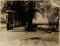
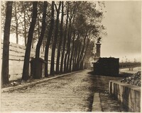
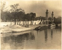
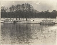
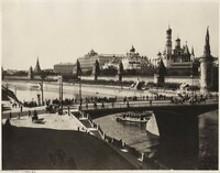
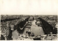
Caption: "River front boulevards in Paris having two levels. The lower level used for river shipping reached by a ramp drive. This is the Quai DOrsay looking toward Alexander III Bridge." (Photograph by R.S. MacElwee)
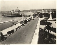
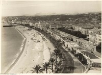
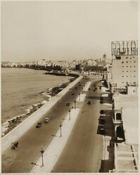
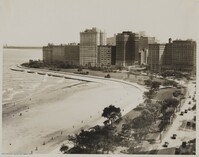
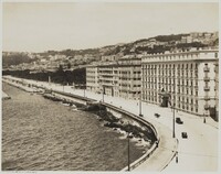
Caption: "Waterfront drive at Nice, France, the Riviera resort. The broad boulevard is the Boulevard Etats Unis (United States). The Casino may be seen on the left in the background." (Photograph by Ewing Galloway)
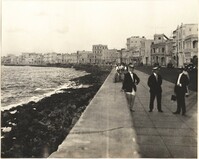
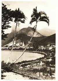
Caption: "Waterfront drive at Botafogo, with Corcovado Peak and less lofty mountains in the background, makes the most beautiful waterfront scene in the world. It is a half circle, and one of many little harbors in Rio de Janeiro."(Photograph by Ewing Galloway).
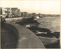
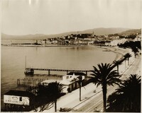
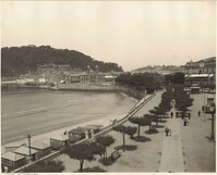
Caption: "Waterfront drive at Cannes, France. Cannes, on French Riviera, has beautiful harbor--famous winter resort. Favorite with tennis fans because big matches are played there." (Photograph by Ewing Galloway)
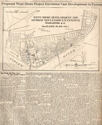
This reprint of a 1929 News and Courier (Charleston, S.C.) article depicts MacElwee's plan for the extension of Murray Boulevard north of the Ashley River bridge. The map and text give detailed descriptions of residential lot sizes in the reclaimed areas, areas for commercial development, parks, etc. and persuasive economic reasons to undertake the development. Though most of the land was eventually reclaimed, no grand boulevard extends north of the Ashley River bridge today and MacElwee's vision of building "one of the most famous water front driveways in the world" was never realized.
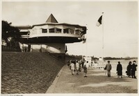
Caption: "Waterfront drive at Cologne, Germany. A novelty in caf construction. This queer building in the form of a bastion is the Rhine Promenade at Cologne." (Photograph by Ewing Galloway)
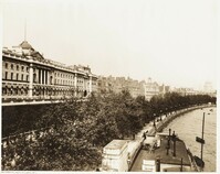
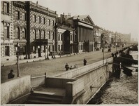
Caption: "Waterfront drive at London. A fine view along the embankment with Somerset House (Government Offices) at left." (Photograph by Ewing Galloway)
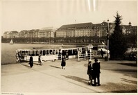
Caption: "Waterfront drive at Hamburg. Alster Damm in Hamburg is an office building street. Office Buildings of the Hamburg American Line at right." (Photograph by Ewing Galloway)
Caption: "Waterfront drive at Rotterdam. A striking general view of the Dutch City. The Haringoleet (canal) and a large portion of the city from the top of a ten story building." (Photograph by Ewing Galloway)
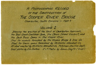
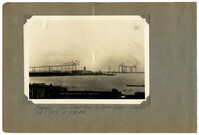
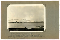
A Photographic Record of the Construction of the Cooper River Bridge; Charleston, South Carolina - 1928-29; Volume I; Showing the erection of the West or Charleston approach, the Town Creek Cantilever Span, the Drum Island Viaduct, and the Deck Truss Spans in the Cooper River. Steel for viaducts furnished by the Virginia Bridge & Iron Co. Steel for truss spans furnished by McClintic-Marshall Co. All steel erected by McClintic-Marshall Co., Pottstown Erection Dep't. Small photos by E.L. Durkee. 5" x 7" Photos by James Smyth ("Irish").;Title Page, 6.75" x 10.125"
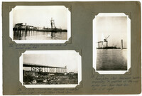
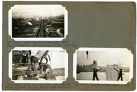
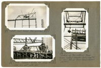
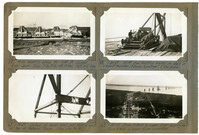
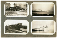
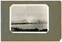
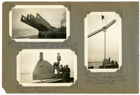
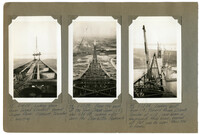
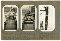
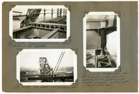
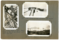
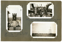
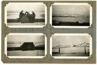
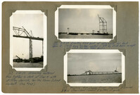
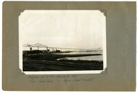
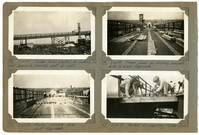
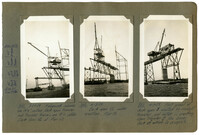
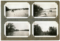
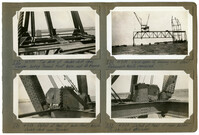
Image #22 (2.75" x 4.5"): "12-13-28. Driving Piles for dock at anchor pier #4."; Image #24 (2.75" x 4.5"): "12-23-28. Charleston Approach completed. Looking east toward Town Creek Span."; Image #25 (4.5" x 2.75"): "1-1-29. Assembling steel falsework bents preparatory to erection of the west anchor arm - Town Creek Span. Pier 2 at right.";Three 4.5" x 2.75" B/W photos numbered 22, 24, 25
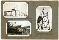
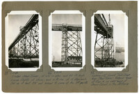
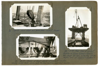
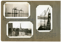
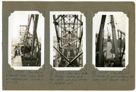
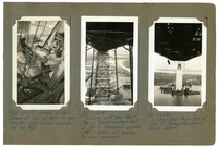
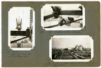
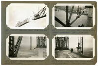
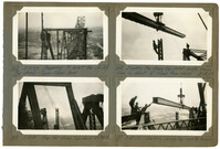
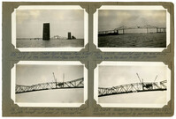
Image #26 (2.75" x 4.5"): " 1-3-29. Erecting first bottom chord section, L0L2, west anchor arm."; Image #27 (4.5" x 2.75"): "1-3-29. Steel falsework bent under L2, west anchor arm. connecting first bottom chord."; Image # 28 (2.75" x 4.5"): "1-2-29. Faslework footing #2 under panel point L4 - west anchor arm.;Three 4.5" x 2.75" B/W photos numbered 26, 27, 28
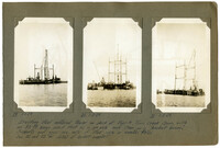
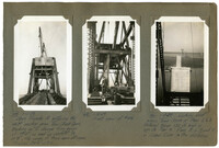
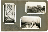
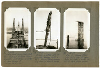
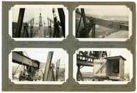
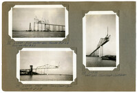
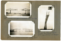
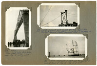
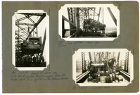
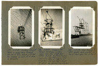
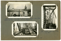
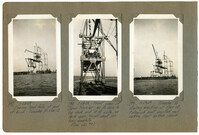
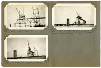
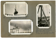
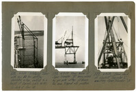
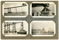
Image #29 (4.5" x 2.75"): "1-1-29."; Image #30 (4.5" x 2.75"): "1-3-29." ; Image #31 (4.5" x 2.75"): "1-3-29." Caption under all pictures: "Erecting steel material tower on deck at Pier 4, Town Creek Span, with an 80 ft. boom used first as a gin pole and then as a 'basket boom.' See 32 and 33 for detail of basket support.";Three 4.5" x 2.75" B/W photos numbered 29, 30, 31
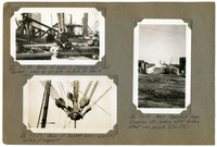
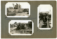
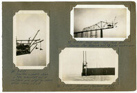
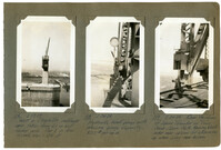
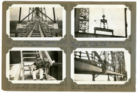
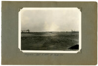
Image #32 (2.75" x 4.5"): "1-1-29. Base of boom in Chicago heel and 'basket', used as gin pole on dock at Pier 4."; Image #33 (2.75" x 4.5"): "1-3-29. Base of "basket boom', showing details of support."; Image #36 (4.5" x 2.75"): "1-6-29. West Approach from America St. looking east, before street was paved. (See 271.)";Three 4.5" x 2.75" B/W photos numbered 32, 33, 36
Image #37 (2.75" x 4.5"): "1-10-29. West Approach, looking west. From top of traveler on west anchor arm of Town Creek Span."; Image #41 (2.75" x 4.5"): "1-10-29. Joint L2, Town Creek Span. Note front bearing of traveler. Tie down rods have been removed and cable used at this particular point only."; Image #40 (2.75" x 4.5"): "1-10-29. Erecting bottom chord L2L4.";Three 4.5" x 2.75" B/W photos numbered 37, 40, 41
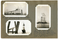
Image #38 (4.5" x 2.75"): "1-10-29."; Image #42 (4.5" x 2.75"): "1-13-29"; Caption under photos 38 & 42: "Timber Stair Tower, 12' x 16' in plan, and 110 ft. high. Eleven flights of stairs, each 10 ft. rise, of 12 steps each. Set up at bent 3W and braced to same at the 3rd points."; Image #43 (4.5" x 2.75"): "1-13-29"; Looking east toward Town Creek from Stair Tower. Material tower at Pier 4, on west bank of Drum Island, in the distance.";Three 4.5" x 2.75" B/W photos numbered 38, 42, 43
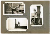
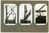
Image #44 (4.5" x 2.75"): "1-13-29. Span Traveler A entering the west anchor arm, Town Creek Span. Blocking up to change from gauge of 19' 6", as used on viaduct, to 18' 0", the gauge of truss span stringers. Trusses 24' 0" c. to c."; Image #45 (4.5" x 2.75"): "1-13-29. Front view of #44."; Image #46 (4.5" x 2.75"): "1-13-29. Looking east across Town Creek at Piers 2 & 3. Material tower 130 ft. high is opposite Pier 4. Piers 5, 6, 7 and 8, in Cooper River, in the distance.";Three 4.5" x 2.75" B/W photos numbered 44, 45, 46
Image #49 (2.75" x 4.5"): "1-18-29. West anchor arm, Town Creek Span. Bottom chord erected to L6."; Image #50 (2.75" x 4.5"): "1-18-29. Erecting top chord U3U5."; Image #51 (4.5" x 2.75"): "1-18-29. Material Tower has erected Anchor Bent on Pier 4 (left), and Bent 1 D of Drum Island Approach (right) with temporary tower bracing b't'n. viaduct traveler trusses, assembled, on lighter at left. (See 57)";Three 4.5" x 2.75" B/W photos numbered 49, 50, 51
Image #52 (4.5" x 2.75"): "1-20-29. From L6, west anchor arm, looking east. Erecting viaduct traveler showing over Pier 3."; Image #53 (4.5" x 2.75"): "1-20-29. Traveler A on the Town Creek Span - rear view."; Image #57 (4.5" x 2.75"): "1-20-29. Erecting viaduct traveler on span 1D.";Three 4.5" x 2.75" B/W photos numbered 52, 53, 57
Image #54 (2.75" x 4.5"): "1-20-29. West anchor Arm completed to L6."; Image #55 (2.75" x 4.5"): "1-20-29. Falsework footing #3 driven thru dock. Under L6, west anchor arm."; Image #58 (4.5" x 2.75"): "1-20-29. Looking up thru material tower toward viaduct traveler being erected on Span 1D, of Drum Island Viaduct. (see #57).";Three 4.5" x 2.75" B/W photos numbered 54, 55, 58
Image #59 (4.5" x 2.75"): "1-20-29. Temporary tower bracing between anchor bent on Pier 4 (left) and bent 1D of Drum Island Viaduct (right). Note the different batter of the two bents, also the diagonal cable bracing, with turnbuckles (Frank Stengel)."; Image #56 (2.75" x 4.5"): "1-20-29. 100 HP Gasoline Hoist #7. Used on viaduct traveler."; Image #60 (2.75" x 4.5"): "1-20-29. Setting shoes on Pier 2.";Three 4.5" x 2.75" B/W photos numbered 56, 59, 60
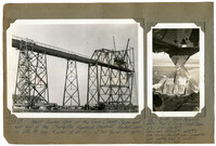
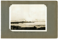
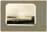
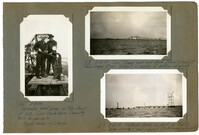
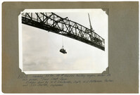
Unnumbered Image (5" x 7"): "1-28-29. West Anchor arm of the Town Creek Span and east end of the Charleston Approach Viaduct. Anchor arm is 256 ft. long (8 panels at 32 ft.). Stair tower at left."; Image #66 (4.5" x 2.75"): "1-30-29. Main bearing shoe, Pier 2, Town Creek Span. 5' 0" x 5' 9" = 28.75 [square feet]. Des. Load = 1,813,000# = 438 # [per square inch]. Erec. Load = 1,089,000# max. (suspended span cantilevered to center). Lower shoe 3' 4" high.";One 4.5" x 2.75" B/W photo and one 5" x 7" B/W photo. Smaller photo numbered 66.
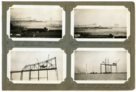
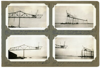
Image #61 (2.75" x 4.5"): "1-23-29. Progress - Town Creek Span. Taken from office tower."; Image #62 (2.75" x 4.5"): "Progress - Town Creek & Drum Island (right). 1-26-29."; Image #63 (2.75" x 4.5"):"1-28-29. West anchor arm complete."; Image #64 (2.75" x 4.5"): "1-28-29. Viaduct traveler starting erection of Drum Island Viaduct. span traveler not yet erected.";Four 4.5" x 2.75" B/W photos numbered 61, 62, 63, 64
Image #65 (2.75" x 4.5"): Main bearing shoes for 1050 ft. Cooper River Span. Base 7' 3" x 8' 6". Wt. 10 tons. Ab't. 4' 6" high."; Image #68 (2.75" x 4.5"): "1-30-29. 100 HP Gas. Hoisting engine on deck of viaduct traveler. 3 Drums & swinger. (Tom Kane)"; Image #67 (2.75" x 4.5"): "1-30-29. Detail of boom heel and foot of mast at top of Material Tower. (See also No. 86)"; Image #69 (2.75" x 4.5"): 1-30-29. Drum Island & Cooper River - looking east. Piers 5 to 13 in Cooper River completed.";Four 4.5" x 2.75" B/W photos numbered 65, 67, 68, 69
Image #70 (2.75" x 4.5"): " 1-30-29. Lead block and boom heel - viaduct traveler."; Image #72 (2.75" x 4.5"): "1-30-29. Detail at front corner of viaduct traveler, showing swivel truck, 40 ton jack, tie-down anchors, and front bearing."; Image #73 (4.5" x 2.5"): "1-30-29. rear view of viaduct traveler on Drum Island Viaduct. Wt. about 80 tons, including 25 ton engine and all rigging & counterw't.";Three 4.5" x 2.75" B/W photos numbered 70, 72, 73
Image #71 (4.5" x 2.75"): "1-30-29. Looking west across Town Creek from west end of Drum Island Viaduct. Just before erection of Span Traveler B. Trusses 24 ft. c. to c."; Image #74 (4.5" x 2.75"): "1-30-29. Driving a batter pile for falsework footings with a No. 2 Vulcan steam hammer hung from a derrick boom."; Image #75 (4.5" x 2.75"): "1-30-29. Pier 12, Cooper River. Elev. top = 50.1 ft. above mean low water. Carries the 270 ft. deck truss spans.";Three 4.5" x 2.75" B/W photos numbered 71, 74, 75
Image #76 (2.75" x 4.5"): Temporary top chord links between U13 and U14, carrying diaphragms for hydraulic jacks - Town Creek Span."; Image #77 (2.75" x 4.5"): "End view of links shown in #76."; Image #78 (2.75" x 4.5): "End view of top chords U12 U13 at U13. (see #87).";Three 4.5" x 2.75" B/W photos numbered 76, 77, 78
Image #79 (2.75" x 4.5"): "150 HP Gasoline hoisting engine (#5 or #6). Weight 31 tons."; Image #80 (2.75" x 4.5"): "100 HP Gasoline hoisting engine (#7). Weight about 26 tons."; Image #81 (2.75" x 4.5"): "Progress 2-1-29."; Image #82 (2.75" x 4.5"): "2-7-29. West cantilever completed to L12. Traveler at L10. Town Creek.";Four 4.5" x 2.75" B/W photos numbered 79, 80, 81, 82
Image #83 (2.75" x 4.5"): "2-7-29. Material Tower erecting Span Traveler B. Viaduct traveler erecting Span 5D - Drum Island Viaduct."; Image #84 (2.75" x 4.5"): "2-7-29. Falsework footings Nos. 4 and 5, east anchor arm - Town Creek."; Image #85 (4.5" x 2.75"): "2-7-29. Steel material Tower F067 & F0187. 40 ft. square x 130 ft. high to boom heels. Two 70 ft. boom (30 ton capacity). On dock opposite Pier 4";Three 4.5" x 2.75" B/W photos numbered 83, 84, 85
Image #87 (2.75" x 4.5"): "2-7-29. Top chords U12 U13 showing joint at U13 and temporary jacking links. Note eye bar hangers."; Image #88 (2.75" x 4.5"): "2-13-29. Bottom chord joint L13 - Town Creek. End joint of suspended span."; Image #89 (4.5" x 2.75"): "2-13-29. Assembly of top chord U12 U13, hanger, U13 L13 and joint L13 at end of suspended span.";Three 4.5" x 2.75" B/W photos numbered 87, 88, 89
Image #90 (4.5" x 2.75"): "2-13-29. Erecting assembly shown in #89, completing end of cantilever arm except for dummy bottom chords L12 L13."; Image #91 (2.75" x 4.5"): "2-13-29. West side - Town Creek Span. Removing steel falsework bent #1 under anchor arm."; Image #92 (2.75" x 4.5"): "2-14-29. Joint and floorbeam at L13 ( = Lo joint of suspended span. See #93).";Three 4.5" x 2.75" B/W photos numbered 90, 91, 92
Image #86 (2.75" x 4.5"): "Detail at boom heel - top of material tower. (See also #67)."; Image #93 (2.75" x 4.5"): "2-14-29. End floorbeam of suspended span erected before last (dummy) bottom chord of cantilever arm is in place."; Image #94 (2.75" x 4.5"): "2-14-29. Detail at front corner of Span Traveler, showing screw bearing jack and tie-down-rods.";Three 4.5" x 2.75" B/W photos numbered 96, 93, 94
Image #95 (2.75" x 4.5"): "2-15-29. Looking down Drum Island Viaduct toward Cooper River. Viaduct Traveler C erecting."; Image #98 (2.75" x 4.5"): "2-22-29. From the peak of the Town Creek Span (U8), elev. 235 ft. looking west down the Charleston Approach."; Image #99 (2.75" x 4.5"): "2-22-29. Looking east from U8, toward Drum Island Traveler at L13, rear boom in foreground. Main boom, boomed out flat, can be seen thru the A-frame.";Three 4.5" x 2.75" B/W photos numbered 95, 98, 99
Image #100 (4.5" x 2.75"): "2-22-29. From U15, on suspended span, looking back at cantilever arm. Traveler is at L13."; Image #101 (4.5" x 2.75"): "2-22-29. View from deck of traveler looking back thru portal and sway bracing of cantilever arm."; Image #102 (4.5" x 2.75"): "2-22-29. View from roof of Traveler A, west cantilever arm, looking east toward Pier 3.";Three 4.5" x 2.75" B/W photos numbered 100, 101, 102
Image #103 (2.75" x 4.5"): "2-22-29. Boomed out, between top chords U14 U16."; Image #104 (2.75" x 4.5"): "2-22-29. Joint U13 - End of the cantilever arm."; Image #105 (2.75" x 4.5"): "2-22-29. Temporary links U13 to U14, b't'n. cantilever arm and suspended span."; Image #112 (2.75" x 4.5"): "2-23-29. Field telephone - top of stair tower at Pier 4.";Four 4.5" x 2.75" B/W photos numbered 103, 104, 105, 112
Image #106 (4.5" x 2.75"): "2-22-29"; Image #107 (4.5" x 2.75"): "2-22-29"; Caption under images 106 & 107: "350 Ton hydraulic jack inside links shown in #105. Looking towards suspended span (left) and towards cantilever arm (right). 10 " [diameter] Pin against which saddle casting bears passes through slotted holes in inside pair of links and its supported by the outside pair, which is riveted to the end of the cantilever arm. Note bearing shims with notch and hole in top, which carry the load while not actually jacking"; Image #117 (4.5" x 2.75"): "2-24-29. Looking straight up at U13 U14.";Three 4.5" x 2.75" B/W photos numbered 106, 107, 117
Image #108 (4.5" x 2.75"): "2-22-29. Detail of lead sheave at heel of boom on span traveler. Note swivel connection (See also #133)."; Image #110 (4.5" x 2.75"): "2-22-29. Looking west from top of Pier 2, toward anchored bent on Pier 1. Falsework columns still in place, but bracing has been removed."; Image #111. (4.5" x 2.75"): "2-22-29. Looking east from top of Pier 2 toward Pier 3 and Drum Island.";Three 4.5" x 2.75" B/W photos numbered 108, 110, 111
Image #113 (2.75" x 4.5"): "2-23-29. East anchor arm. Traveler Bat L4 Truss erected to L6."; Image #114 (2.75" x 4.5"): "2-23-29. West side - Town Creek Span. Traveler A at L15."; Image #115 (4.5" x 2.75"): "2-23-29. West side - Town Creek Cantilever.";Three 4.5" x 2.75" B/W photos numbered 113, 114, 115
Image #116 (4.5" x 2.75"): "2-23-29. West or Charleston cantilever arm taken from L6 on east anchor arm. Pier 3 in foreground, elev. = 134ft."; Image #118 (4.5" x 2.75"): "2-24-29. Hydraulic hand pump with pressure gauge. Capacity, 8000# per sq. in."; Image #119 (4.5" x 2.75"): "2-24-29. rear tie-down of Span Traveler on Town Creek Span. Note bearing block under rear column for shimming up when using rear boom.";Three 4.5" x 2.75" B/W photos numbered 116, 118, 119
Image #120 (2.75" x 4.5"): "2-24-29. Expansion joint at L0. Plates supported on pipe separators."; Image #128 (2.75" x 4.5"): "3-3-29. Top chord - west cantilever arm."; Image #121 (4.5" x 2.75"): "2-24-29. Rocker shoe under end of viaduct girder, providing expansion between anchor arm and viaduct. Supported on cross girder at top of anchor bent.";Three 4.5" x 2.75" B/W photos numbered 120, 121, 128
Image #122 (2.75" x 4.5"):"2-24-29. West cantilever arm erected to L17 L18 - Traveler at L15."; Image #124 (2.75" x 4.5"): "2-25-29. Traveler A at L16, its farthest position."; Image #123 (2.75" x 4.5"): "2-24-29. East anchor arm erected to L6. Traveler at L6. Viaduct traveler at right."; Image #125 (2.75" x 4.5"): "2-25-29. East anchor arm at Pier 3.";Four 4.5" x 2.75" B/W photos numbered 122, 123, 124, 125
Image #126 (4.5" x 2.75"):"3-1-29. Starting erection of east cantilever arm, from L18, the center of the channel."; Image #129 (2.75" x 4.5"): "3-3-29. From top of Pier 2 showing underside of floor system."; Image #130 (2.75" x 4.5"): "3-3-29. Pier 3 and the Cooper River, from top of Pier 2.";Three 4.5" x 2.75" B/W photos numbered 126, 129, 130
Image #133 (4.5" x 2.75"): "3-3-29 Detail of lead sheave block at heel of span traveler main boom. See #108."; Image #135 (2.75" x 4.5"): "3-3-29. Detail at top of A-frame. Span traveler."; Image #136 (2.75" x 4.5"): "3-3-29. Progress - Town Creek Span.";Three 4.5" x 2.75" B/W photos numbered 133, 135, 136
Image #137 (4.5" x 2.75"): "3-7-29. Looking west from the east cantilever arm."; Image #138 (2.75" x 4.5"): "3-7-29. Erecting bottom laterals."; Image #139 (2.75" x 4.5"): "3-7-29. Material track laid on mud sills on Drum Island.";Three 4.5" x 2.75" B/W photos numbered 137, 138, 139
Image #140 (2.75" x 4.5"): "3-7-29. Material truck supported on piling. Drum Island Approach."; Image #141 (2.75" x 4.5"): "3-7-29. 'Billy' the Drum Island mascot, at top of stair tower with Buckholt."; Image #142 (2.75" x 4.5"): "3-7-29. Balance beam for handling plate girders. Length 10ft."; Image #146 (2.75" x 4.5"): "3-11-29. Support & tie-down for sill of stiffleg derrick at Pier 4.";Four 4.5" x 2.75" B/W photos numbered 140, 141, 142, 146
Image #143 (4.5" x 2.75"): "3-7-29. Stiffleg derrick used as material hoist on top of span at Pier 4, to feed viaduct traveler (in distance). Near stiffleg sticks thru truss (#146) and far leg is on viaduct (#145)."; Image #144 (4.5" x 2.75"): #3-7-29. Detail at heel of stiffleg derrick SO4383 (See #167)."; Image #145 (4.5" x 2.75"): "3-7-29. Tie-down and strut supporting end of stiffleg projecting outside viaduct girder (See #143).";Three 4.5" x 2.75" B/W photos numbered 143, 144, 145
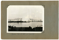
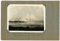
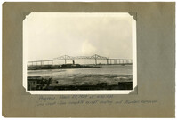
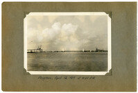
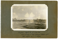
Unnumbered Image (5" x 7"): Progress March 8, 1929 at 4:30 P.M. West (left) half of Town Creek Span completed and traveler being dismantled. Viaduct traveler erecting span 17D. East cantilever arm complete.";One 5" x 7" B/W photo
Image #147 (4.5" x 2.75"): "3-11-29. West half of Town Creek Span complete, as seen from end of east cantilever arm."; Image #148 (2.75" x 4.5"): "3-11-29. Picking 150 HP Gas. Hoist, 31 tons, from traveler to dismantle traveler and lower engine to deck."; Image #149 (2.75" x 4.5"): "3-11-29. Erecting material tower on dock at Pier 13.";Three 4.5" x 2.75" B/W photos numbered 147, 148, 149
Image #150 (2.75" x 4.5"): "Erecting east half of suspended span - Town Creek."; Image #152 (2.75" x 4.5"): "3-13-29. Progress in Town Creek - getting nearer!"; Image #151 (2.75" x 4.5"): "3-11-29. West cantilever as seen from below. This photo suggested by C.D. Marshall.";Three 4.5" x 2.75" B/W photos numbered 150, 151, 152
Image #153 (2.75" x 4.5"): "3-13-29. One more panel to be erected."; Image #154 (2.75" x 4.5"): "3-13-29. Ready to erect the first closing bottom chord."; Image #155 (2.75" x 4.5"): "3-13-29. Erecting the closing bottom chord - south truss - Town Creek Span."; Image #158 (2.75" x 4.5"): "3-13-29. Erecting the closing bottom chord - north truss - Town Creek Span.";Three 4.5" x 2.75" B/W photos numbered 153, 154, 155, 158
Image #159 (2.75" x 4.5"): "3-13-29. The closing bottom chord joint at L17! Member on left has slotted hole at pin."; Image #160 (2.75" x 4.5"): " Closing joint at L17! 4" slotted hole allows erection of closing chord at any temperature."; Image #161 (2.75" x 4.5"): "3-13-29 Progress."; Image #162 (2.75" x 4.5"): "3-3-29. Closing bottom chords in place.";Four 4.5" x 2.75" B/W photos numbered 159, 160, 161, 162
Image #163 (2.75" x 4.5"): "3-15-29. Preparing to erect the closing top chords - Town Creek Span."; Image #164 (2.75" x 4.5"): "3-15-29. Gap for closing top chord U16 U18."; Image #165 (2.75" x 4.5"): "Erecting the closing top chord - south truss. Gap is about 2" longer than chord. 3-15-29."; Image #171 (2.75" x 4.5"): "3-15-29. Erecting closing top - north truss.";Four 4.5" x 2.75" B/W photos numbered 163, 164, 165, 171
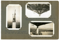
Image #166 (4.5" x 2.75"): "3-15-29. Hydraulic hand pump on top chord at U13, Town Creek Span. Capacity 8000 lbs. Per sq. in. 'Swede' Nelson and V.I. Varga."; Image #168 (2.75" x 4.5"): "3-15-29. Town Creek Span and Drum Island Viaduct from Cooper River. Viaduct is nearly at bottom of grade."; Image #169 (2.75" x 4.5"): "3-15-29. Material tower on dock at Pier 13. One boom erected and rigged. (50 ft. boom, on right).";Three 4.5" x 2.75" B/W photos numbered 166, 168, 169
Image #167 (4.5" x 2.75"): "3-15-29. Unloading material from lighters to dock at Pier 4 with stiffleg derrick, for the Drum Island viaduct. (See #143.)"; Image #172 (2.75" x 4.5"): "3-17-29. Erecting first bent of false work for deck span 12. (70 ft. boom has been erected, on left, by 50 ft. boom on right and which has been taken down)."; Image #173 (2.75" x 4.5"): "3-17-29. Progress - from Cooper River. Traveler A removed. Drum Island Viaduct at bottom of grade.";Three 4.5" x 2.75" B/W photos numbered 167, 172, 173
Image #174 (2.75" x 4.5"): "3-17-29. Town Creek Span between Piers 9 (left) and 8 of the Cooper River Span. Looking west."; Image #175 (2.75" x 4.5"): "3-12-29. Suspended Span swung (3-16-29) and complete except last panel of floor system."; Image #176 (2.75" x 4.5"): 3-20-29. Suspended span has been swung. Note gap in top chord to right of traveler."; Image #177 (2.75" x 4.5"): 3-20-29. Temporary top chord jacking links U13 U14 removed to be replaced by permanent 'dummy' chords.";Four 4.5" x 2.75" B/W photos numbered 174, 175, 176, 177
Image #178 (4.5" x 2.75"): "3-17-29. Town Creek Span, from below, near Pier 3 - looking west."; Image #179 (2.75" x 4.5"): "3-17-29. Falsework bent for deck span #12, taken from the East Approach Viaduct permanent steel for temporary use."; Image #180 (2.75" x 4.5"): "3-20-29. First panel of deck span #12 erected by material tower at Pier 13. Pier 12 at left.";Three 4.5" x 2.75" B/W photos numbered 178, 179, 180
Image #181 (2.75" x 4.5"): "3-20-29. Detail of shoe at top of falsework bent under deck span."; Image #182 (2.75" x 4.5"): "3-17-29. Fuel oil compressor - (semi-diesel)."; Image #201 (2.75" x 4.5"): "4-1-29. End View of #181."; Image #183 (2.75" x 4.5"): "3-20-29. Twist in 40 ft. viaduct girder due to improper loading for shipment.";Four 4.5" x 2.75" B/W photos numbered 181, 182, 183, 201
Image #184 (4.5" x 2.75"): "3-22-29. Ready to lower the first 150 HP gasoline hoisting engine from the bridge deck to a lighter in the stream below."; Image #185 (2.75" x 4.5"): "3-22-29. Same as #184 - front view."; Image #186 (2.75" x 4.5"): "3-22-29. Starting down.";Three 4.5" x 2.75" B/W photos numbered 184, 185, 186
Unnumbered Image (5" x 7"): "Lowering 33 ton, 150 HP Gasoline hoisting engine, under its own power. Town Creek Span. Ridden down by W.E. Omohundro, Sup't., W.S. Patterson, Pusher, and John Shelton, Engineman.";One 5" x 7" B/W photo
Image #187 (4.5" x 2.75"): "3-22-29. Looking straight down on engine being lowered. One set of falls, 8 parts, with lead line snatched so lead off of drum is horizontal."; Image #188 (4.5" x 2.75"): " 3-28-29. Lowering the second 150 HP gas. hoisting engine from Town Creek Span. ridden down by Dougherty (Eng'm'n.), Omohundro, Leatherman, and two bridgemen. Note two sets of 5-part falls and lead lines straight up off of the drums. (See 195 & 196)"; Image #189 (4.5" x 2.75"): "3-27-29. Span Traveler A, with double deck, erected on top of deck span #12, at Pier 13.";Three 4.5" x 2.75" B/W photos numbered 187, 188, 189
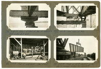
Image #190 (2.75" x 4.5"): "3-26-29. Timber forms erected for curbing, on West Approach. Concrete plant at right."; Image #191 (2.75" x 4.5"): "3-26-29. Timber forms for pouring concrete deck on West Approach."; Image #192 (2.75" x 4.5"): "3-26-29. Pouring concrete deck. West Approach."; Image #193 (2.75" x 4.5"): "3-26-29. Method of supporting timber forms.";Four 4.5" x 2.75" B/W photos numbered 190, 191, 192, 193
Image #194 (2.75" x 4.5"): "3-27-29. From top of Pier 6, looking toward Drum Island viaduct and Town Creek Span. Pier 5 in foreground."; Image #195 (2.75" x 4.5"): "Second 150 HO gas. Engine starting down thru deck of Town Creek Span. (See 188)"; Image #196 (4.5" x 2.75"): "3-28-29. rear view of #195. (See 188)";Three 4.5" x 2.75" B/W photos numbered 194, 195, 196
Unnumbered Image (5" x 7"): "Progress, March 29, 1929 at 4:30 P.M. Town Creek Span complete except riveting and travelers removed.";One 5" x 7" B/W photo
Image #197 (4.5" x 2.75"): "3-28-29. Reaving load falls at end of boom - Traveler A - Pier 13."; Image #198 (4.5" x 2.75"): "3-28-29. Front view of Span Traveler, 40 ft. high to top deck and 18 ft. wide, on deck span. Weight about 150 tons, complete. (See also #4)."; Image #199 (4.5" x 2.75"): "3-29-29. Traveler A starting erection at Pier 13. Falsework bent erected and setting first bottom chord.";Three 4.5" x 2.75" B/W photos numbered 197, 198, 199
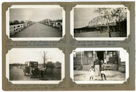
Image #208 (2.75" x 4.5"): "3-30-29. The Santee River Bridge, 2.2 miles long, between McClellanville & Georgetown, S.C."; Image #209 (2.75" x 4.5"): "3-30-29. 200 ft. Swing Span over the North Santee. All our piling came thru this channel."; Image #212 (2.75" x 4.5"): "3-30-29. The 'Chariot' - McC. M. Co's official car. Used by our piling inspectors in the Santee Swamps."; Image #213 (2.75" x 4.5"): "3-30-29. A negro 'mammy' storekeeper.";Four 4.5" x 2.75" B/W photos numbered 208, 209, 212, 213
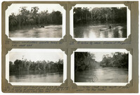
Image #214 (2.75" x 4.5"): "3-30-29. Flooded country as seen from the Santee River Bridge."; Image #215 (2.75" x 4.5"): "3-30-29. Rafts of cypress piling tied up below the Santee River Bridge - ready for towing to Charleston."; Image #216 (2.75" x 4.5"): "3-30-29. Up the North Santee - flooded over its banks."; Image #217 (2.75" x 4.5"): "3-30-29. Chicken Creek - a tributary of the North Santee - narrow and swift.";Four 4.5" x 2.75" B/W photos numbered 214, 215, 216, 217
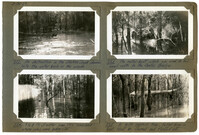
Image #218 (2.75" x 4.5"): "3-30-29. Negro wood-cutters enroute home for the week end."; Image #219 (2.75" x 4.5"): "3-30-29. A hollow-log canoe. Duncan at the paddle."; Image #220 (2.75" x 4.5"): "3-30-29. Laurel Hill Island - water 2 to 3 ft. deep over the 5 ft. banks at normal stage. Most of the 85 ft. and 90 ft. piling came from here."; Image #221 (2.75" x 4.5"): "3-30-29. Chicken Creek - note height of water around the tree trunks.";Four 4.5" x 2.75" B/W photos numbered 218, 219, 220, 221
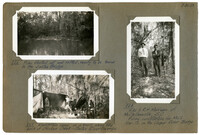
Image #222 (2.75" x 4.5"): "3-30-29. An obstruction in the Chicken Creek channel. Note the water back in the woods."; Image #223 (2.75" x 4.5"): "3-30-29. The motor boat which was used to tow small rafts to the Santee Bridge."; Image #224 (2.75" x 4.5"): "3-30-29. 7 to 8 Ft. of water over the 'mainland' where piles were being cut."; Image #225 (2.75" x 4.5"): "3-30-29. A 90 ft. cypress tree, felled from a boat. Must be cleared and floated out.";Four 4.5" x 2.75" B/W photos numbered 222, 223, 224, 225
Image #226 (2.75" x 4.5"): "3-30-29. Piles floated out and rafted, ready to be towed to the Santee Bridge."; Image #227 (2.75" x 4.5"): "3-30-29. Woodcutters camp on a knoll along the bank of Chicken Creek - Santee River Swamps."; Image #228 (2.75" x 4.5"): "3-30-29. H.W. & R.H. Morrison of McClellanville, S.C. Piling contractors for McCl. Mar. Co. on the Cooper River Bridge.";Three 4.5" x 2.75" B/W photos numbered 226, 227, 228
Image #230 (2.75" x 4.5"): "4-7-29. Top deck of double-deck Span Traveler, looking toward front boom and A-frame."; Image #231 (2.75" x 4.5"): "4-7-29. Detail at heel of main (front) boom. Double-deck span traveler."; Image #234 (2.75" x 4.5"): "4-7-29. Deckspan 12 swung and steel falsework bents removed."; Image #233 (2.75" x 4.5"): "4-7-29. Detail at heel of rear boom. Double-deck traveler.";Four 4.5" x 2.75" B/W photos numbered 230, 231, 233, 234
Image #236 (2.75" x 4.5"): "4-7-29. Rear view of Viaduct Traveler 'C' erecting Span Traveler 'A' on Span 5."; Image #237 (2.75" x 4.5"): "4-7-29. Side view of #236."; Image #232 (4.5" x 2.75"): "4-7-29. Top deck of double-deck Span Traveler A, looking toward rear boom, A-frame and backstay connection.";Three 4.5" x 2.75" B/W photos numbered 232, 236, 237
Image #235 (4.5" x 2.75"): "4-7-29. Material Tower with two 50 ton stiffleg derricks on top, erected to a height of 3 panels (ab't 95 ft.) On dock at Pier 13."; Image #238 (4.5" x 2.75"): "4-9-29. Main boom of Span Traveler 'B' being raised by gin pole after A-frame has been tripped into position."; Image #239 (4.5" x 2.75"): "4-9-29. From deck of Viaduct Traveler 'C', erecting Span Traveler 'B'.";Three 4.5" x 2.75" B/W photos numbered 235, 238, 239
Unnumbered Image (5" x 7"): "Progress, April 19, 1929 at 4:30 P.M. Note east end of East Approach (extreme right) under erection by C.E. Hillyer.";One 5" x 7" B/W photo
Image #240 (2.75" x 4.5"): "4-9-29. Compressor plant under Span 35D, near Pier 5, and ramp leading to it from Pier 37D which is in deep water."; Image #242 (2.75" x 4.5"): "4-18-29. Falsework under Span 5. Falsework bents have battered columns."; Image #241 (2.75" x 4.5"): "4-18-29. Rocker bearing and roller expansion shoe under 270 ft. deck truss span - Pier 6."; Image #243 (2.75" x 4.5"): "4-15-29. Span 5 erected to U5L6.";Four 4.5" x 2.75" B/W photos numbered 240, 241, 242, 243