Picturing the Bridge. The story of the Cooper river bridge as told in the special editions of the Charleston newspapers was rendered vivid by the wealth of illustrations in those publications, showing progress of the work on the great structure from the beginning to the moment of opening. These pictures will make interesting history and will doubtless be shown in years to come by many of those who participated in the jubilation of yesterday and will be keen to tell of the celebration to the youngsters who will take it all for granted that there is a driveway across the Cooper for their cars. The engineers and builders of the bridge, as, indeed, all of the officers of the corporation which owns and of the contractors who built it, cooperated in every possible way with the newspapers in the making of the special editions complete records of the work and of the occasion celebrated at the opening, and to them The Evening Post expresses its appreciation and thanks. Especially is it under obligations to Mr. E. L. Durkee, engineer of the McClintic-Marshall Company, for putting at its disposal his extensive collection of photographs of the work during the various stages of its progress. The pictures tell the story of the bridge as no verbal description could and there are virtually no significant phases of the work which escaped Mr. Durkee's camera. To have had access to this collection was the good fortune of The Evening Post and of the public to whom it was enabled to present them.;Newspaper clipping (6.5"" x 2"") from the Charleston Evening Post, titled ""Picturing the Bridge.""
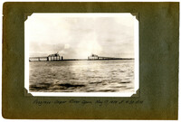
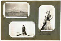
A Photographic Record of the Construction of the Cooper River Bridge; Charleston, South Carolina - 1928-29; Volume II; Showing the erection of the Cooper River Cantilever Span, 1050 feet center to center of main piers, and being at the time of its completion the fifth longest cantilever, or truss span of any kind in the world. Steel furnished by McClintic-Marshall Co. and erected by the Pottstown Erection Dep't. Small photos by E.L. Durkee. 5" x 7" Photos by James Smyth ("Irish"). Larger photos as noted.;Title Page, 6.75" x 10.125"
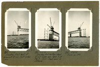
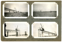
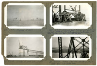
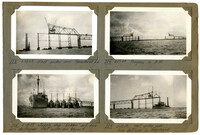
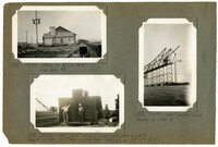
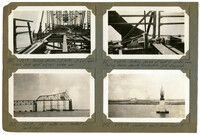
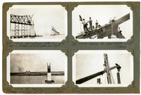
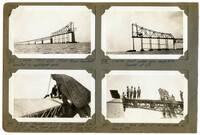
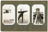
Image #289 (2.75" x 4.5"): "5-3-29. Erecting first bent of falsework at L2, East anchor arm."; Image #290 (2.75" x 4.5"): "5-3-29. Erecting first bottom chord of west anchor arm, Span 7, at Pier 7. Town Creek span in distance."; Image #292 (2.75" x 4.5"): "Same as 290.";Three 4.5" x 2.75" B/W photos numbered 289, 290, 292
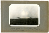
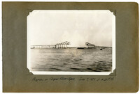
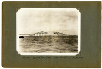
Unnumbered Image (5" x 7"): "Progress in Cooper River, May 3, 1929 at 4:30 P.M. East Approach (right) complete except two spans.";One 5" x 7" B/W photo
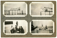
Image #291 (4.5" x 2.75"): "5-3-29. East Approach nearing completion."; Image #294 (4.5" x 2.75"): "5-5-29. First panel of truss erected - west anchor arm."; Image #295 (4.5" x 2.75"): "5-6-29. Erecting first panel of floor - east anchor arm."; Image #297 (4.5" x 2.75"): "5-6-29. Progress in Cooper River.";Four 4.5" x 2.75" B/W photos numbered 291, 294, 295, 297
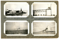
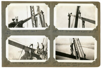
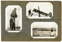
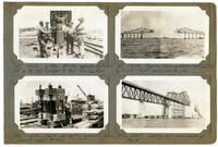
Image #298 (2.75" x 4.5"): "5-6-29. Our tank lighter and coal barge."; Image #299 (2.75" x 4.5"): "5-6-29. Traveler "B" moved out to L2. West anchor arm."; Image #300 (2.75" x 4.5"): "5-8-29. Second panel--west anchor arm complete. Traveler Bat L3, erecting portal bracing."; Image #301 (2.75" x 4.5"): "5-9-29. Traveler B erecting third falsework bent at L6, west anchor arm.";Four 4.5" x 2.75" B/W photos numbered 298, 299, 300, 301
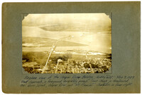
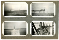
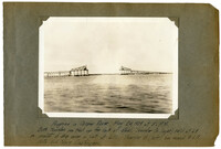
Unnumbered Image (5" x 7"): "Airplane view of the Cooper River Bridge - looking east. May 9, 1929. West approach, in foreground, completely paved. Town Creek in foreground, then Drum Island, Cooper River, and Mt. Pleasant. Charleston in lower right.";One 5" x 7" B/W photo
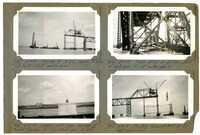
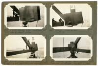
Image #302 (2.75" x 4.5"): "5-9-29. Traveler B at L2, ready to move out to L3. East anchor arm."; Image #304 (2.75" x 4.5"): "5-9-29. Field office on bottom chord of deck span 10 - at anchor pier 10."; Image #305 (2.75" x 4.5"): "5-9-29. Looking west from traveler B toward traveler A. Town Creek span at left."; Image # 307 (2.75" x 4.5"): " 5-9-29. Erecting falsework bent at L6 - west anchor arm.";Four 4.5" x 2.75" B/W photos numbered 302, 304, 305, 307
Image #308 (2.75" x 4.5"): "5-9-29. Progress at noon."; Image #309 (2.75" x 4.5"): "5-9-29. Falsework bent #29, L6 - west anchor arm. Low tide, 25 ft. of water. 16 plumb piles & 8 batter piles under each column. Max. load = 20 1/2 tons per pile."; Image #310 (2.75" x 4.5"): "5-10-29. Traveler A, east side, at L4."; Image #311 (2.75" x 4.5"): " 5-10-29. Looking west from traveler on Cooper River Span, west anchor arm.";Four 4.5" x 2.75" B/W photos numbered 308, 309, 310, 311
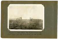
Unnumbered Image (5" x 7"): "Progress in Cooper River, May 10, 1929, at 4:30 P.M. East viaduct (right) has been completed and viaduct traveler removed.";One 5" x 7" B/W photo
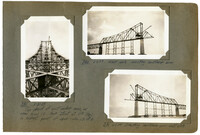
Image #312 (2.75" x 4.5"): "5-16-29. Progress in Cooper River."; Image #313 (2.75" x 4.5"): "5-16-29. West anchor arm - Span 7."; Image #314 (2.75" x 4.5"): "5-16-29. Looking east from traveler B on west anchor arm. Pier B in foreground, Elev. 132.0'."; Image #319 (2.75" x 4.5"): "5-16-29. Looking down on Span Traveler.";Four 4.5" X 2.75" B/W photos numbered 312, 313, 314, 319
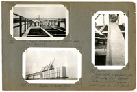
Image #320 (2.75" x 4.5"): "5-17-29. Setting timber forms for concrete deck, East Approach."; Image #321 (4.5" x 2.75"); "5-17-29. Bowed plates in expansion joint at 9E on the East Approach. Taken to illustrate shop error. report made to V.B. & Iron Co."; Image #322 (2.75" x 4.5"): "5-17-29. Progress in Cooper River.";Three 4.5" X 2.75" B/W photos numbered 320, 321, 322
Image #323 (2.75" x 4.5"): "5-17-29. East anchor arm. Traveler at L6."; Image #324 (2.75" x 4.5"): "5-17-29. Progress in A.M."; Image #325 (2.75" x 4.5"): "5-18-29. Supply ship "Dobbin" and five Navy destroyers. West anchor arm beyond."; Image #329 (2.75" x 4.5"): "5-18-29. West anchor arm. Navy destroyer in foreground.";Four 4.5" x 2.75" B/W photos numbered 323, 324, 325, 329
Image #330 (2.75" x 4.5"): "5-18-29. Progress"; Image #331 (2.75" x 4.5"): "5-18-29. West anchor arm. Note stair tower and office on bottom chord of deck span - at Pier 7."; Image #332 (4.5" x 2.75"): "5-18-29. Deck of bridge from end of east anchor arm. Traveler at L6.";Three 4.5" x 2.75" B/W photos numbered 330, 331, 332
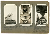
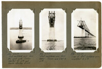
Image #333 (2.75" x 4.5"): "5-18-29. Falsework bent 31- L8 - East anchor arm. 16 Plumb piles and 10 battered piles under each col. 40 ft. of water at low tide. Taken at low tide. See also 355."; Image #334 (2.75" x 4.5"): "5-18-29. Falsework footing 32 - L6, anchor arm. Similar to bent 31. Max. load 20 1/2 tons per pile (D + L + Trav.)."; Image #335 (4.5" x 2.75"): "5-18-29. Looking west from top of anchor pier 10 showing steel falsework. Pier 9 beyond = 450 ft. Bents at 90 ft. centers. Flswk. cols. plumb and 37'-6" c. to c.";Three 4.5" x 2.75" B/W photos numbered 333, 334, 335
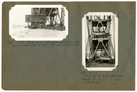
Image #336 (2.75" x 4.5"): "5-18-29. Office in A.C.L. Yard. See also #1."; Image #337 (2.75" x 4.5"): "Bottom chord joint at L10 - over main piers 8 and 9. Weight 13 tons. 12'-7" long x 12'-4" high (Main gas. pl. 108" x 1" x 12'-7")."; Image #338 (4.5" x 2.75"): "5-21-29. West anchor arm landing on Pier 8.";Three 4.5" x 2.75" B/W photos numbered 336, 337, 338
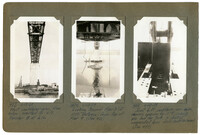
Image #339 (2.75" x 4.5"): "5-21-29. West anchor arm ready to erect last panel 8-10, and land on main pier 8."; Image #340 (2.75" x 4.5"): "5-22-29. East anchor arm erecting last panel 8-10, to land on main pier 9."; Image #341 (2.75" x 4.5"): "5-22-29. Setting shoe in Pier 8. wt. of lower shoe = 10 tons. Base 7'-3 x 8'-6 = 61.6 [square feet]"; Image #342 (2.75" x 4.5"): "5-22-29. Setting main shoes on Pier 8.";Four 4.5" x 2.75" B/W photos numbered 339, 340, 341, 342
Image #343 (2.75" x 4.5"): "5-22-29. Erecting bottom chord joint at L10, Pier 8. Weight 13 tons."; Image #344 (2.75" x 4.5"): "5-22-29. Same as 343. (Leatherman)."; Image #345 (2.75" x 4.5"): "5-22-29. Pulling joint L10 back into place to connect to bott. chord L8 L10 and diagonal M9 L10."; Image #348 (2.75" x 4.5"): "5-23-29. Bottom chord joint L10 before erection of stringers. Floorbeam in place.";Four 4.5" x 2.75" B/W photos numbered 343, 344, 345, 348
Image #346 (4.5" x 2.75"): " 5-22-29. East anchor arm just before erecting the joints at L10 on Pier 8. (See also 343, 344, 345, & 348)."; Image #347 (4.5" x 2.75"): "Traveler on floorbeam at L8, Span 7, from Pier 8."; Image #349 (4.5" x 2.75"): "5-23-29. Main bearing shoe, Pier 9. Anchor arm trusses not yet pulled back to connect to top shoe. See pulling and jacking devices, 350 and 351. 7'-3 x 8'-6 = 61.6 [square feet]. Max. Des. Load = 3,916,000 [pounds] = 63,540 [pounds/square feet] = 440 [pounds/square inch]. Max. Erec. Load = 2,658,000 [pounds] with suspended span cantilevered to center.";Three 4.5" x 2.75" B/W photos numbered 346, 347, 349
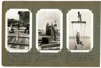
Image #350 (2.75" x 4.5"): "5-23-29. Pulling device (at left) at L0 - Span 9. Where deck span adjoins anchor arm."; Image #351 (2.75" x 4.5"): "5-23-29. Jacking device at end of anchor arm. Pulling device, showing turnbuckle - just beyond."; Image #352 (2.75" x 4.5"): "5-23-29. West anchor arm landed on Pier 8 (right)."; Image #353 (2.75" x 4.5"): "5-24-29. Looking west from Span 9.";Four 4.5" x 2.75" B/W photos numbered 350, 351, 352, 353
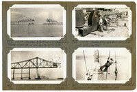
Unnumbered Image (5" x 7"): "Progress in Cooper River, May 24, 1929 at 5: P.M. Both travelers are tied up for lack of steel. Traveler A (right) held at L8 on account of shop error in joint at L10. Traveler B (left) has moved to L9. Note U.S. Navy destroyers.";One 5" x 7" B/W photo
Image #354 (2.75" x 4.5"): "5-26-29. Deck spans 10, 11, and 12 - from stair tower at Pier 10. Trusses are 40 ft. deep."; Image #355 (2.75" x 4.5"): "5-26-29. Looking down from deck of bridge at falsework footing #31, under L8. Span 9. (See 333)."; Image #356 (2.75" x 4.5"): "5-26-29. Same as 355."; Image # 5-26-29. Falsework footing #32, under L6, Span 9. (See also 334).";Four 4.5" x 2.75" B/W photos numbered 354, 355, 356, 357
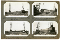
Image #360 (2.75" x 4.5"): "5-28-29. rolling top chord U8 U10 - 100 ft. long Wt. 36 tons."; Image #361 (2.75" x 4.5"): "5-28-29. U8 U10 being rolled right side up for erection. Note special rolling slings & sheaves."; Image #362 (2.75" x 4.5"): "5-28-29. Loading U8 U10 on truck to be run out and loaded on lighter."; Image #363 (2.75" x 4.5"): "5-28-29. Loading U8 U10 on lighter.";Four 4.5" x 2.75" B/W photos numbered 360, 361, 362, 363
Image #364 (2.75" x 4.5"): "5-28-29. East anchor arm (left) - Town Creek Span in distance and west anchor arm (right)."; Image #365 (2.75" x 4.5"): "5-29-29. Town Creek Span & west anchor arm of Cooper River Span with U8 U10 just erected."; Image #366 (2.75" x 4.5"): "5-29-29. Erecting top chord U8 U10. Span 9. (Patterson)."; Image #367 (2.75" x 4.5"): "5-29-29. Erecting U8 U10. Span 9.";Four 4.5" X 2.75" B/W photos numbered 364, 365, 366, 367
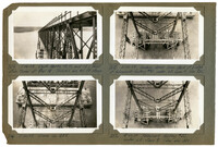
Image #372 (2.75" x 4.5"): "5-29-29. Looking down from U10, over Pier 8. Elev. = 280 ft. above water. Note lighter with steel."; Image #373 (4.5" x 2.75"): "5-29-29. Top chord U8 U10 just entered into joint at U8 and ready to be pulled in and connected. Span 9.";Two 4.5" x 2.75" B/W photos numbered 372, 373
Image #377 (2.75" x 4.5"): "5-29-29. West side. First truss members erected in cantilever arm."; Image #378 (2.75" x 4.5"): "5-29-29. East anchor arm complete. Traveler at L9."; Image #379 (2.75" x 4.5"): "5-31-29. Traveler at L9 erecting peak strut at U10. Then moves back 15 ft. to allow boom to "duck" under strut and move forward.. Not drift."; Image #380 (2.75" x 4.5"): "5-31-29. Peak strut at U10 east side, as shown in 379.";Four 4.5" x 2.75" B/W photos numbered 377, 378, 379, 380
Image #382 (2.75" x 4.5"): "5-31-29. Erecting peak strut at U10 west side, by hauling it around in the back of the boom. Traveler at L10."; Image #383 (4.5" x 2.75"): "5-31-29. Final position of 382. Erecting strut in this manner took about 2 hours as compared with 10 minutes for method shown in 379."; Image #384 (2.75" x 4.5"): "5-31-29. Looking west from U10 on east side.";Three 4.5" x 2.75" B/W photos numbered 382, 383, 384
Unnumbered Image (5" x 7'): "Progress in Cooper River, May 31, 1929 at 4:30 P.M. Lost 3 days since May 24 on account of lack of steel.";One 5" x 7" B/W photo
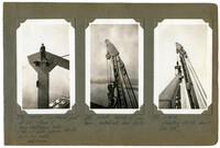
Image #381 (4.5" x 2.75"): "5-31-29. Top chord of east anchor arm, as seen from U1. Peak strut at U10 (top) is highest point of span - elev. 280 ft."; Image #385 (2.75" x 4.5"): "6-1-29. West side - erecting cantilever arm."; Image #386 (2.75" x 4.5"): "6-1-29. Erecting cantilever arm - east side.";Three 4.5" x 2.75" B/W photos numbered 381, 385, 386
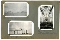
Image #387 (2.75" x 4.5"): "Progress 6-1-29"; Image #388 (2.75" x 4.5"): "6-3-29. E.L.D. at U10, watching erection of top chord U10 U12, east side. (See 390 & 391)."; Image #389 (4.5" x 2.75"): "6-2-29. Starting erection of east cantilever arm.";Three 4.5" x 2.75" B/W photos numbered 387, 388, 389
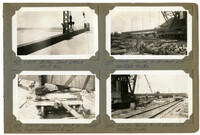
Image #395 (2.75" x 4.5"): "6-6-29. Heel of main boom - upper deck of Span Traveler."; Image #398 (4.5" x 2.75"): "6-6-29. West cantilever arm, from Pier 9. U12 L12 at right."; Image #401 (2.75" x 4.5"): "6-6-29. Looking west from end of the east causeway. Town Creek Span (left) is nearly 1 3/4 miles away.";Three 4.5" x 2.75" B/W photos numbered 395, 398, 401
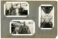
Image #399 (2.75" x 4.5") and Image #400 (2.75" x 4.5"): "Member U12 L12 East Cantilever Arm. 96'-0" c. to c. panel points. As erected this member appeared to be 3 1/2" short, due to fabrication of members, some shorter and some longer than their final geometric lengths, and due to the sub-diagonal M11 L12 (lower right). Pulled together by a 7-part auxiliary falls. Engine kept in high gear to reduce power - max. lead line pull = about 9000 [pounds], approx., giving possible capacity of 130 tons. Required one day to connect each member - two days total.;Two 4.5" x 2.75" B/W photos numbered 399, 400
Image #397 (4.5" x 2.75"): "6-6-29. Main boom - span Traveler. 100 ft. long c. to c. pins. Taken from near heel looking up towards tip at U12."; Image #403 (2.75" x 4.5"): "6-6-29. Setting reinforcing steel - east approach."; Image #404 (2.75" x 4.5"): "6-6-29. 4 Ton Gas. Locomotive & dump cars for pouring concrete deck, east approach & causeway.";Three 4.5" x 2.75" B/W photos numbered 397, 403, 404
Image #405 (2.75" x 4.5"): "6-7-29. Erecting stringers - east cantilever."; Image #406 (2.75" x 4.5"): "6-8-29. Crane 19. 40 Ton capacity. Working weight about 100 tons."; Image #407 (2.75" x 4.5"): "6-8-29. Dummies made up to throw off of top of span as practice drill for life savers."; Image #409 (2.75" x 4.5"): "6-8-29. Town Creek Span with advertising sign 13' x 30' in place at center.";Four 4.5" x 2.75" B/W photos numbered 405, 406, 407, 409
Image #414 (2.75" x 4.5"): "6-10-29. Balance beam with special bent hitch plates used for short hitch on high lifts wher [sic] drift is small."; Image #415 (4.5" x 2.75"): "6-11-29. Front view of double-deck span traveler A at L12 on east cantilever arm.";Two 4.5" x 2.75" B/W photos numbered 414, 415
Image #416 (4.5" x 2.75"): "6-11-29. East cantilever arm, from the west side. Trusses erected to L14 and traveler standing at L12."; Image #417 (4.5" x 2.75"): "6-11-29. East cantilever arm from below. Trusses are erected to L14."; Image #418 (4.5" x 2.75"): "6-11-29. View of East cantilever arm, completed to L14.";Three 4.5" x 2.75" B/W photos numbered 416, 417, 418
Image #419 (4.5" x 2.75"): "6-11-29. Expansion plate on East Approach showing bend in plane of plate due to punching and riveting along one edge only. Bowed 1 3/4" in 20 ft. Straightened by hammering along other edge."; Image #420 (4.5" x 2.75"): "6-12-29. Assembling eye-bars to bottom chord joint L17. (See also 424)."; Image #421 (4.5" x 2.75"): "6-12-29. Entering pin at U17 connecting eye-bars supporting suspended span to end of cantilever arm.";Three 4.5" x 2.75" B/W photos numbered 419, 420, 421
Image #422 (2.75" x 4.5"): "6-11-29. Traveler B (left) at L15 & truss to L16. Traveler A (east side) at L12 and truss to L14."; Image #423 (2.75" x 4.5"): "6-12-29. West cantilever arm complete except floor L16 to L17. Eye-bar hangers U17 L17 being erected."; Image #424 (2.75" x 4.5"): "6-12-29. Assembling eye-bars U17 L17 to joint L17 (See 420)."; Image #425 (2.75" x 4.5"): "6-12-29. Driving 10" pin at U17 with 500lb. overhauling ball - west cantilever arm.";Four 4.5" x 2.75" B/W photos numbered 422, 423, 424, 425
Image #426 (4.5" x 2.75"): "6-12-29. West cantilever arm complete to L16 U17 and hangers U17 L17 for support of suspended span erected, together with joint L17."; Image #427 (4.5" x 2.75"): "6-12-29. Joint U17 with dummy extension carrying 10" pin hole for jacking pin, etc., for controlling cantilever erection of the suspended span. (Geo. Schnell)."; Image #428 (4.5" x 2.75"): "6-12-29. Portal at entrance to the west anchor arm. Deck truss span 6 in foreground.";Three 4.5" x 2.75" B/W photos numbered 426, 427, 428
Image #429 (2.75" x 4.5"): "6-11-29. Lifting 500 ton capacity hydraulic jack by its 12 1/2" [diameter] plunger to test the section."; Image #430 (2.75" x 4.5"): "6-12-29. Frame for testing hydraulic jacks. Capacity about 50 tons."; Image #431 (2.75" x 4.5"): "6-13-29. Progress. West cantilever (left) complete to U17 L17. Right (east) arm to L16."; Image #432 (2.75" x 4.5"): "6-12-29. Looking east from south of Pier 5.";Four 4.5" x 2.75" B/W photos numbered 429, 430, 431, 432
Image #433 (4.5" x 2.75"): "6-13-29. West cantilever arm, from below, erected to L17. Traveler B at L16."; Image #434 (4.5" x 2.75"): "6-13-29. Looking toward Pier 8 (at 1050' distance) from top of Pier 9. (See 431)."; Image #435 (4.5" x 2.75"): "6-13-29. Joint L17, cantilever arm side, showing opening for 10" [diameter] jacking pin and for jack, to control suspended span while cantilevered. (See 488).";Three 4.5" x 2.75" B/W photos numbered 433, 434, 435
Image #437 (2.75" x 4.5"): "6-13-29. Bottom chord L14 L16. Wt. 17 tons."; Image #438 (2.75" x 4.5"): "6-14-29. Turntable truck for turning long truss members end for end."; Image #439 (2.75" x 4.5"): "6-14-29. Turning 90 ft. chord with turntable trucks."; Image #440 (2.75" x 4.5"): "6-14-29. Turning 90 ft. chord with turntable trucks.";Four 4.5" x 2.75" B/W photos numbered 437, 438, 439, 440