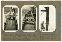
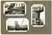
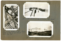
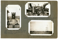
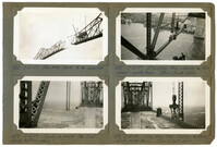
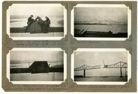
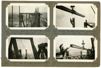
Image #106 (4.5" x 2.75"): "2-22-29"; Image #107 (4.5" x 2.75"): "2-22-29"; Caption under images 106 & 107: "350 Ton hydraulic jack inside links shown in #105. Looking towards suspended span (left) and towards cantilever arm (right). 10 " [diameter] Pin against which saddle casting bears passes through slotted holes in inside pair of links and its supported by the outside pair, which is riveted to the end of the cantilever arm. Note bearing shims with notch and hole in top, which carry the load while not actually jacking"; Image #117 (4.5" x 2.75"): "2-24-29. Looking straight up at U13 U14.";Three 4.5" x 2.75" B/W photos numbered 106, 107, 117
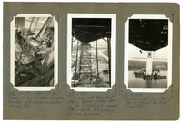
Image #108 (4.5" x 2.75"): "2-22-29. Detail of lead sheave at heel of boom on span traveler. Note swivel connection (See also #133)."; Image #110 (4.5" x 2.75"): "2-22-29. Looking west from top of Pier 2, toward anchored bent on Pier 1. Falsework columns still in place, but bracing has been removed."; Image #111. (4.5" x 2.75"): "2-22-29. Looking east from top of Pier 2 toward Pier 3 and Drum Island.";Three 4.5" x 2.75" B/W photos numbered 108, 110, 111
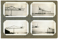
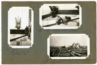
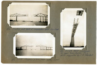
Image #113 (2.75" x 4.5"): "2-23-29. East anchor arm. Traveler Bat L4 Truss erected to L6."; Image #114 (2.75" x 4.5"): "2-23-29. West side - Town Creek Span. Traveler A at L15."; Image #115 (4.5" x 2.75"): "2-23-29. West side - Town Creek Cantilever.";Three 4.5" x 2.75" B/W photos numbered 113, 114, 115
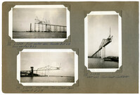
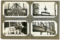
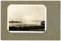
Image #116 (4.5" x 2.75"): "2-23-29. West or Charleston cantilever arm taken from L6 on east anchor arm. Pier 3 in foreground, elev. = 134ft."; Image #118 (4.5" x 2.75"): "2-24-29. Hydraulic hand pump with pressure gauge. Capacity, 8000# per sq. in."; Image #119 (4.5" x 2.75"): "2-24-29. rear tie-down of Span Traveler on Town Creek Span. Note bearing block under rear column for shimming up when using rear boom.";Three 4.5" x 2.75" B/W photos numbered 116, 118, 119
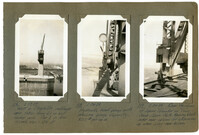
Image #120 (2.75" x 4.5"): "2-24-29. Expansion joint at L0. Plates supported on pipe separators."; Image #128 (2.75" x 4.5"): "3-3-29. Top chord - west cantilever arm."; Image #121 (4.5" x 2.75"): "2-24-29. Rocker shoe under end of viaduct girder, providing expansion between anchor arm and viaduct. Supported on cross girder at top of anchor bent.";Three 4.5" x 2.75" B/W photos numbered 120, 121, 128
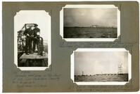
Image #122 (2.75" x 4.5"):"2-24-29. West cantilever arm erected to L17 L18 - Traveler at L15."; Image #124 (2.75" x 4.5"): "2-25-29. Traveler A at L16, its farthest position."; Image #123 (2.75" x 4.5"): "2-24-29. East anchor arm erected to L6. Traveler at L6. Viaduct traveler at right."; Image #125 (2.75" x 4.5"): "2-25-29. East anchor arm at Pier 3.";Four 4.5" x 2.75" B/W photos numbered 122, 123, 124, 125
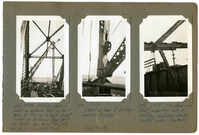
Image #126 (4.5" x 2.75"):"3-1-29. Starting erection of east cantilever arm, from L18, the center of the channel."; Image #129 (2.75" x 4.5"): "3-3-29. From top of Pier 2 showing underside of floor system."; Image #130 (2.75" x 4.5"): "3-3-29. Pier 3 and the Cooper River, from top of Pier 2.";Three 4.5" x 2.75" B/W photos numbered 126, 129, 130
Image #133 (4.5" x 2.75"): "3-3-29 Detail of lead sheave block at heel of span traveler main boom. See #108."; Image #135 (2.75" x 4.5"): "3-3-29. Detail at top of A-frame. Span traveler."; Image #136 (2.75" x 4.5"): "3-3-29. Progress - Town Creek Span.";Three 4.5" x 2.75" B/W photos numbered 133, 135, 136
Image #137 (4.5" x 2.75"): "3-7-29. Looking west from the east cantilever arm."; Image #138 (2.75" x 4.5"): "3-7-29. Erecting bottom laterals."; Image #139 (2.75" x 4.5"): "3-7-29. Material track laid on mud sills on Drum Island.";Three 4.5" x 2.75" B/W photos numbered 137, 138, 139
Image #140 (2.75" x 4.5"): "3-7-29. Material truck supported on piling. Drum Island Approach."; Image #141 (2.75" x 4.5"): "3-7-29. 'Billy' the Drum Island mascot, at top of stair tower with Buckholt."; Image #142 (2.75" x 4.5"): "3-7-29. Balance beam for handling plate girders. Length 10ft."; Image #146 (2.75" x 4.5"): "3-11-29. Support & tie-down for sill of stiffleg derrick at Pier 4.";Four 4.5" x 2.75" B/W photos numbered 140, 141, 142, 146
Image #143 (4.5" x 2.75"): "3-7-29. Stiffleg derrick used as material hoist on top of span at Pier 4, to feed viaduct traveler (in distance). Near stiffleg sticks thru truss (#146) and far leg is on viaduct (#145)."; Image #144 (4.5" x 2.75"): #3-7-29. Detail at heel of stiffleg derrick SO4383 (See #167)."; Image #145 (4.5" x 2.75"): "3-7-29. Tie-down and strut supporting end of stiffleg projecting outside viaduct girder (See #143).";Three 4.5" x 2.75" B/W photos numbered 143, 144, 145
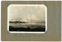
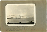
Unnumbered Image (5" x 7"): Progress March 8, 1929 at 4:30 P.M. West (left) half of Town Creek Span completed and traveler being dismantled. Viaduct traveler erecting span 17D. East cantilever arm complete.";One 5" x 7" B/W photo
Image #147 (4.5" x 2.75"): "3-11-29. West half of Town Creek Span complete, as seen from end of east cantilever arm."; Image #148 (2.75" x 4.5"): "3-11-29. Picking 150 HP Gas. Hoist, 31 tons, from traveler to dismantle traveler and lower engine to deck."; Image #149 (2.75" x 4.5"): "3-11-29. Erecting material tower on dock at Pier 13.";Three 4.5" x 2.75" B/W photos numbered 147, 148, 149
Image #150 (2.75" x 4.5"): "Erecting east half of suspended span - Town Creek."; Image #152 (2.75" x 4.5"): "3-13-29. Progress in Town Creek - getting nearer!"; Image #151 (2.75" x 4.5"): "3-11-29. West cantilever as seen from below. This photo suggested by C.D. Marshall.";Three 4.5" x 2.75" B/W photos numbered 150, 151, 152
Image #153 (2.75" x 4.5"): "3-13-29. One more panel to be erected."; Image #154 (2.75" x 4.5"): "3-13-29. Ready to erect the first closing bottom chord."; Image #155 (2.75" x 4.5"): "3-13-29. Erecting the closing bottom chord - south truss - Town Creek Span."; Image #158 (2.75" x 4.5"): "3-13-29. Erecting the closing bottom chord - north truss - Town Creek Span.";Three 4.5" x 2.75" B/W photos numbered 153, 154, 155, 158
Image #159 (2.75" x 4.5"): "3-13-29. The closing bottom chord joint at L17! Member on left has slotted hole at pin."; Image #160 (2.75" x 4.5"): " Closing joint at L17! 4" slotted hole allows erection of closing chord at any temperature."; Image #161 (2.75" x 4.5"): "3-13-29 Progress."; Image #162 (2.75" x 4.5"): "3-3-29. Closing bottom chords in place.";Four 4.5" x 2.75" B/W photos numbered 159, 160, 161, 162
Image #163 (2.75" x 4.5"): "3-15-29. Preparing to erect the closing top chords - Town Creek Span."; Image #164 (2.75" x 4.5"): "3-15-29. Gap for closing top chord U16 U18."; Image #165 (2.75" x 4.5"): "Erecting the closing top chord - south truss. Gap is about 2" longer than chord. 3-15-29."; Image #171 (2.75" x 4.5"): "3-15-29. Erecting closing top - north truss.";Four 4.5" x 2.75" B/W photos numbered 163, 164, 165, 171
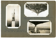
Image #166 (4.5" x 2.75"): "3-15-29. Hydraulic hand pump on top chord at U13, Town Creek Span. Capacity 8000 lbs. Per sq. in. 'Swede' Nelson and V.I. Varga."; Image #168 (2.75" x 4.5"): "3-15-29. Town Creek Span and Drum Island Viaduct from Cooper River. Viaduct is nearly at bottom of grade."; Image #169 (2.75" x 4.5"): "3-15-29. Material tower on dock at Pier 13. One boom erected and rigged. (50 ft. boom, on right).";Three 4.5" x 2.75" B/W photos numbered 166, 168, 169
Limit your search
Photographic Record of the Cooper River Bridge✖[remove]202