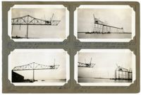
Image #122 (2.75" x 4.5"):"2-24-29. West cantilever arm erected to L17 L18 - Traveler at L15."; Image #124 (2.75" x 4.5"): "2-25-29. Traveler A at L16, its farthest position."; Image #123 (2.75" x 4.5"): "2-24-29. East anchor arm erected to L6. Traveler at L6. Viaduct traveler at right."; Image #125 (2.75" x 4.5"): "2-25-29. East anchor arm at Pier 3.";Four 4.5" x 2.75" B/W photos numbered 122, 123, 124, 125
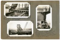
Image #120 (2.75" x 4.5"): "2-24-29. Expansion joint at L0. Plates supported on pipe separators."; Image #128 (2.75" x 4.5"): "3-3-29. Top chord - west cantilever arm."; Image #121 (4.5" x 2.75"): "2-24-29. Rocker shoe under end of viaduct girder, providing expansion between anchor arm and viaduct. Supported on cross girder at top of anchor bent.";Three 4.5" x 2.75" B/W photos numbered 120, 121, 128
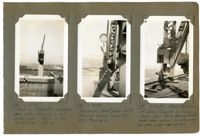
Image #116 (4.5" x 2.75"): "2-23-29. West or Charleston cantilever arm taken from L6 on east anchor arm. Pier 3 in foreground, elev. = 134ft."; Image #118 (4.5" x 2.75"): "2-24-29. Hydraulic hand pump with pressure gauge. Capacity, 8000# per sq. in."; Image #119 (4.5" x 2.75"): "2-24-29. rear tie-down of Span Traveler on Town Creek Span. Note bearing block under rear column for shimming up when using rear boom.";Three 4.5" x 2.75" B/W photos numbered 116, 118, 119
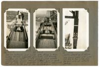
Image #106 (4.5" x 2.75"): "2-22-29"; Image #107 (4.5" x 2.75"): "2-22-29"; Caption under images 106 & 107: "350 Ton hydraulic jack inside links shown in #105. Looking towards suspended span (left) and towards cantilever arm (right). 10 " [diameter] Pin against which saddle casting bears passes through slotted holes in inside pair of links and its supported by the outside pair, which is riveted to the end of the cantilever arm. Note bearing shims with notch and hole in top, which carry the load while not actually jacking"; Image #117 (4.5" x 2.75"): "2-24-29. Looking straight up at U13 U14.";Three 4.5" x 2.75" B/W photos numbered 106, 107, 117
Limit your search
Photographic Record of the Cooper River Bridge✖[remove]4