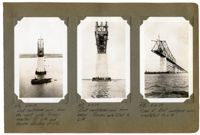
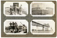
Image #416 (4.5" x 2.75"): "6-11-29. East cantilever arm, from the west side. Trusses erected to L14 and traveler standing at L12."; Image #417 (4.5" x 2.75"): "6-11-29. East cantilever arm from below. Trusses are erected to L14."; Image #418 (4.5" x 2.75"): "6-11-29. View of East cantilever arm, completed to L14.";Three 4.5" x 2.75" B/W photos numbered 416, 417, 418
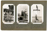
Image #419 (4.5" x 2.75"): "6-11-29. Expansion plate on East Approach showing bend in plane of plate due to punching and riveting along one edge only. Bowed 1 3/4" in 20 ft. Straightened by hammering along other edge."; Image #420 (4.5" x 2.75"): "6-12-29. Assembling eye-bars to bottom chord joint L17. (See also 424)."; Image #421 (4.5" x 2.75"): "6-12-29. Entering pin at U17 connecting eye-bars supporting suspended span to end of cantilever arm.";Three 4.5" x 2.75" B/W photos numbered 419, 420, 421
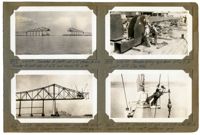
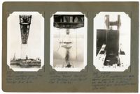
Image #422 (2.75" x 4.5"): "6-11-29. Traveler B (left) at L15 & truss to L16. Traveler A (east side) at L12 and truss to L14."; Image #423 (2.75" x 4.5"): "6-12-29. West cantilever arm complete except floor L16 to L17. Eye-bar hangers U17 L17 being erected."; Image #424 (2.75" x 4.5"): "6-12-29. Assembling eye-bars U17 L17 to joint L17 (See 420)."; Image #425 (2.75" x 4.5"): "6-12-29. Driving 10" pin at U17 with 500lb. overhauling ball - west cantilever arm.";Four 4.5" x 2.75" B/W photos numbered 422, 423, 424, 425
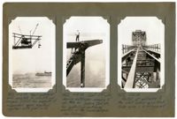
Image #426 (4.5" x 2.75"): "6-12-29. West cantilever arm complete to L16 U17 and hangers U17 L17 for support of suspended span erected, together with joint L17."; Image #427 (4.5" x 2.75"): "6-12-29. Joint U17 with dummy extension carrying 10" pin hole for jacking pin, etc., for controlling cantilever erection of the suspended span. (Geo. Schnell)."; Image #428 (4.5" x 2.75"): "6-12-29. Portal at entrance to the west anchor arm. Deck truss span 6 in foreground.";Three 4.5" x 2.75" B/W photos numbered 426, 427, 428
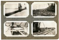
Image #429 (2.75" x 4.5"): "6-11-29. Lifting 500 ton capacity hydraulic jack by its 12 1/2" [diameter] plunger to test the section."; Image #430 (2.75" x 4.5"): "6-12-29. Frame for testing hydraulic jacks. Capacity about 50 tons."; Image #431 (2.75" x 4.5"): "6-13-29. Progress. West cantilever (left) complete to U17 L17. Right (east) arm to L16."; Image #432 (2.75" x 4.5"): "6-12-29. Looking east from south of Pier 5.";Four 4.5" x 2.75" B/W photos numbered 429, 430, 431, 432
Image #433 (4.5" x 2.75"): "6-13-29. West cantilever arm, from below, erected to L17. Traveler B at L16."; Image #434 (4.5" x 2.75"): "6-13-29. Looking toward Pier 8 (at 1050' distance) from top of Pier 9. (See 431)."; Image #435 (4.5" x 2.75"): "6-13-29. Joint L17, cantilever arm side, showing opening for 10" [diameter] jacking pin and for jack, to control suspended span while cantilevered. (See 488).";Three 4.5" x 2.75" B/W photos numbered 433, 434, 435
Image #437 (2.75" x 4.5"): "6-13-29. Bottom chord L14 L16. Wt. 17 tons."; Image #438 (2.75" x 4.5"): "6-14-29. Turntable truck for turning long truss members end for end."; Image #439 (2.75" x 4.5"): "6-14-29. Turning 90 ft. chord with turntable trucks."; Image #440 (2.75" x 4.5"): "6-14-29. Turning 90 ft. chord with turntable trucks.";Four 4.5" x 2.75" B/W photos numbered 437, 438, 439, 440
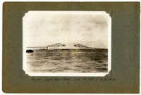
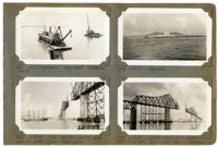
Image #411 (2.75" x 4.5"): "6-18-29. U.S. Engineers' Snag-boat 'Wateree.'"; Image #442 (2.75" x 4.5"): "6-18-29. Four-masted sailing ship passing under Cooper River Span."; Image #443 (2.75" x 4.5"): "6-17-29. Progress."; Image #444 (2.75" x 4.5"): "6-18-29. Looking west from Cooper River. Pier 10 at left. Town Creek Span in background.";Four 4.5" x 2.75" B/W photos numbered 441, 442, 443, 444
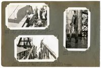
Image #445 (2.75" x 4.5"): "6-18-29. Joint L17 - end of suspended span. Note 3" [diameter] pin and slotted hole for expansion."; Image #446 (2.75" x 4.5"): "6-18-29. Pulling piles using Union No. 2 steam hammer, inverted, and taking a strain with 3-part falls by "Wateree"."; Image #447 (4.5" x 2.75"): "6-18-29. Ready to pull.";Three 4.5" x 2.75" B/W photos numbered 445, 446, 447