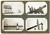
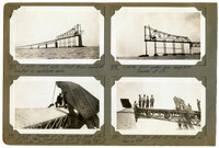
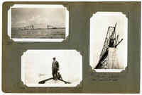
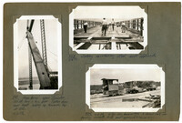
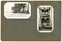
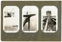
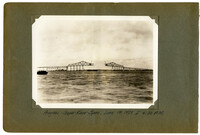
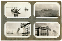
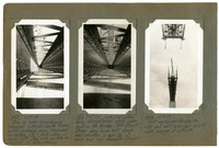
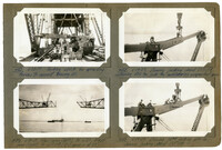
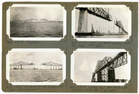
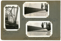
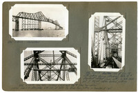
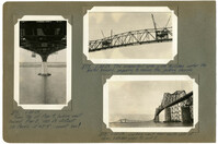
Image #364 (2.75" x 4.5"): "5-28-29. East anchor arm (left) - Town Creek Span in distance and west anchor arm (right)."; Image #365 (2.75" x 4.5"): "5-29-29. Town Creek Span & west anchor arm of Cooper River Span with U8 U10 just erected."; Image #366 (2.75" x 4.5"): "5-29-29. Erecting top chord U8 U10. Span 9. (Patterson)."; Image #367 (2.75" x 4.5"): "5-29-29. Erecting U8 U10. Span 9.";Four 4.5" X 2.75" B/W photos numbered 364, 365, 366, 367
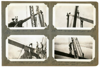
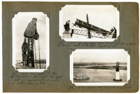
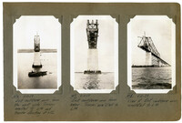
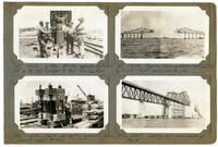
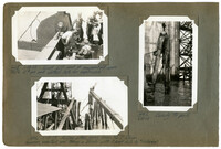
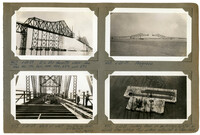
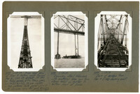
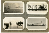
Image #372 (2.75" x 4.5"): "5-29-29. Looking down from U10, over Pier 8. Elev. = 280 ft. above water. Note lighter with steel."; Image #373 (4.5" x 2.75"): "5-29-29. Top chord U8 U10 just entered into joint at U8 and ready to be pulled in and connected. Span 9.";Two 4.5" x 2.75" B/W photos numbered 372, 373
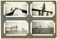
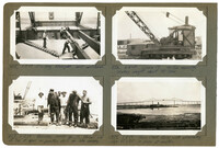
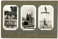
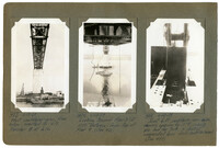
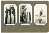
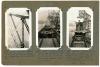
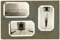
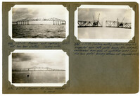
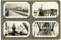
Image #377 (2.75" x 4.5"): "5-29-29. West side. First truss members erected in cantilever arm."; Image #378 (2.75" x 4.5"): "5-29-29. East anchor arm complete. Traveler at L9."; Image #379 (2.75" x 4.5"): "5-31-29. Traveler at L9 erecting peak strut at U10. Then moves back 15 ft. to allow boom to "duck" under strut and move forward.. Not drift."; Image #380 (2.75" x 4.5"): "5-31-29. Peak strut at U10 east side, as shown in 379.";Four 4.5" x 2.75" B/W photos numbered 377, 378, 379, 380
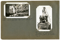
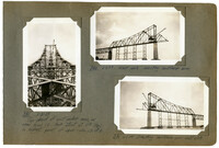
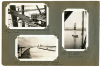
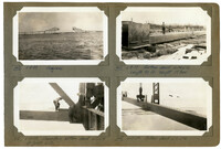
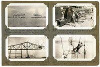
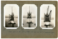
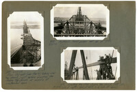
Image #382 (2.75" x 4.5"): "5-31-29. Erecting peak strut at U10 west side, by hauling it around in the back of the boom. Traveler at L10."; Image #383 (4.5" x 2.75"): "5-31-29. Final position of 382. Erecting strut in this manner took about 2 hours as compared with 10 minutes for method shown in 379."; Image #384 (2.75" x 4.5"): "5-31-29. Looking west from U10 on east side.";Three 4.5" x 2.75" B/W photos numbered 382, 383, 384
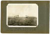
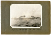
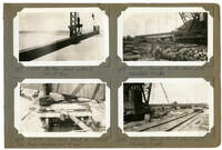
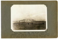
Unnumbered Image (5" x 7'): "Progress in Cooper River, May 31, 1929 at 4:30 P.M. Lost 3 days since May 24 on account of lack of steel.";One 5" x 7" B/W photo
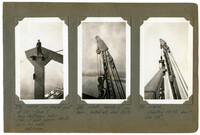
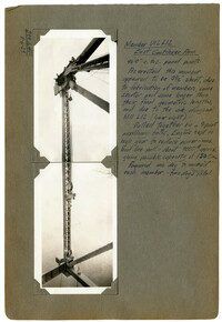
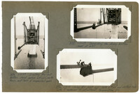
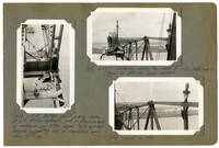
Image #381 (4.5" x 2.75"): "5-31-29. Top chord of east anchor arm, as seen from U1. Peak strut at U10 (top) is highest point of span - elev. 280 ft."; Image #385 (2.75" x 4.5"): "6-1-29. West side - erecting cantilever arm."; Image #386 (2.75" x 4.5"): "6-1-29. Erecting cantilever arm - east side.";Three 4.5" x 2.75" B/W photos numbered 381, 385, 386
Image #387 (2.75" x 4.5"): "Progress 6-1-29"; Image #388 (2.75" x 4.5"): "6-3-29. E.L.D. at U10, watching erection of top chord U10 U12, east side. (See 390 & 391)."; Image #389 (4.5" x 2.75"): "6-2-29. Starting erection of east cantilever arm.";Three 4.5" x 2.75" B/W photos numbered 387, 388, 389
Image #395 (2.75" x 4.5"): "6-6-29. Heel of main boom - upper deck of Span Traveler."; Image #398 (4.5" x 2.75"): "6-6-29. West cantilever arm, from Pier 9. U12 L12 at right."; Image #401 (2.75" x 4.5"): "6-6-29. Looking west from end of the east causeway. Town Creek Span (left) is nearly 1 3/4 miles away.";Three 4.5" x 2.75" B/W photos numbered 395, 398, 401
Image #399 (2.75" x 4.5") and Image #400 (2.75" x 4.5"): "Member U12 L12 East Cantilever Arm. 96'-0" c. to c. panel points. As erected this member appeared to be 3 1/2" short, due to fabrication of members, some shorter and some longer than their final geometric lengths, and due to the sub-diagonal M11 L12 (lower right). Pulled together by a 7-part auxiliary falls. Engine kept in high gear to reduce power - max. lead line pull = about 9000 [pounds], approx., giving possible capacity of 130 tons. Required one day to connect each member - two days total.;Two 4.5" x 2.75" B/W photos numbered 399, 400
Image #397 (4.5" x 2.75"): "6-6-29. Main boom - span Traveler. 100 ft. long c. to c. pins. Taken from near heel looking up towards tip at U12."; Image #403 (2.75" x 4.5"): "6-6-29. Setting reinforcing steel - east approach."; Image #404 (2.75" x 4.5"): "6-6-29. 4 Ton Gas. Locomotive & dump cars for pouring concrete deck, east approach & causeway.";Three 4.5" x 2.75" B/W photos numbered 397, 403, 404
Image #405 (2.75" x 4.5"): "6-7-29. Erecting stringers - east cantilever."; Image #406 (2.75" x 4.5"): "6-8-29. Crane 19. 40 Ton capacity. Working weight about 100 tons."; Image #407 (2.75" x 4.5"): "6-8-29. Dummies made up to throw off of top of span as practice drill for life savers."; Image #409 (2.75" x 4.5"): "6-8-29. Town Creek Span with advertising sign 13' x 30' in place at center.";Four 4.5" x 2.75" B/W photos numbered 405, 406, 407, 409
Image #414 (2.75" x 4.5"): "6-10-29. Balance beam with special bent hitch plates used for short hitch on high lifts wher [sic] drift is small."; Image #415 (4.5" x 2.75"): "6-11-29. Front view of double-deck span traveler A at L12 on east cantilever arm.";Two 4.5" x 2.75" B/W photos numbered 414, 415
Image #416 (4.5" x 2.75"): "6-11-29. East cantilever arm, from the west side. Trusses erected to L14 and traveler standing at L12."; Image #417 (4.5" x 2.75"): "6-11-29. East cantilever arm from below. Trusses are erected to L14."; Image #418 (4.5" x 2.75"): "6-11-29. View of East cantilever arm, completed to L14.";Three 4.5" x 2.75" B/W photos numbered 416, 417, 418
Image #419 (4.5" x 2.75"): "6-11-29. Expansion plate on East Approach showing bend in plane of plate due to punching and riveting along one edge only. Bowed 1 3/4" in 20 ft. Straightened by hammering along other edge."; Image #420 (4.5" x 2.75"): "6-12-29. Assembling eye-bars to bottom chord joint L17. (See also 424)."; Image #421 (4.5" x 2.75"): "6-12-29. Entering pin at U17 connecting eye-bars supporting suspended span to end of cantilever arm.";Three 4.5" x 2.75" B/W photos numbered 419, 420, 421
Image #422 (2.75" x 4.5"): "6-11-29. Traveler B (left) at L15 & truss to L16. Traveler A (east side) at L12 and truss to L14."; Image #423 (2.75" x 4.5"): "6-12-29. West cantilever arm complete except floor L16 to L17. Eye-bar hangers U17 L17 being erected."; Image #424 (2.75" x 4.5"): "6-12-29. Assembling eye-bars U17 L17 to joint L17 (See 420)."; Image #425 (2.75" x 4.5"): "6-12-29. Driving 10" pin at U17 with 500lb. overhauling ball - west cantilever arm.";Four 4.5" x 2.75" B/W photos numbered 422, 423, 424, 425
Image #426 (4.5" x 2.75"): "6-12-29. West cantilever arm complete to L16 U17 and hangers U17 L17 for support of suspended span erected, together with joint L17."; Image #427 (4.5" x 2.75"): "6-12-29. Joint U17 with dummy extension carrying 10" pin hole for jacking pin, etc., for controlling cantilever erection of the suspended span. (Geo. Schnell)."; Image #428 (4.5" x 2.75"): "6-12-29. Portal at entrance to the west anchor arm. Deck truss span 6 in foreground.";Three 4.5" x 2.75" B/W photos numbered 426, 427, 428
Image #429 (2.75" x 4.5"): "6-11-29. Lifting 500 ton capacity hydraulic jack by its 12 1/2" [diameter] plunger to test the section."; Image #430 (2.75" x 4.5"): "6-12-29. Frame for testing hydraulic jacks. Capacity about 50 tons."; Image #431 (2.75" x 4.5"): "6-13-29. Progress. West cantilever (left) complete to U17 L17. Right (east) arm to L16."; Image #432 (2.75" x 4.5"): "6-12-29. Looking east from south of Pier 5.";Four 4.5" x 2.75" B/W photos numbered 429, 430, 431, 432
Image #433 (4.5" x 2.75"): "6-13-29. West cantilever arm, from below, erected to L17. Traveler B at L16."; Image #434 (4.5" x 2.75"): "6-13-29. Looking toward Pier 8 (at 1050' distance) from top of Pier 9. (See 431)."; Image #435 (4.5" x 2.75"): "6-13-29. Joint L17, cantilever arm side, showing opening for 10" [diameter] jacking pin and for jack, to control suspended span while cantilevered. (See 488).";Three 4.5" x 2.75" B/W photos numbered 433, 434, 435
Image #437 (2.75" x 4.5"): "6-13-29. Bottom chord L14 L16. Wt. 17 tons."; Image #438 (2.75" x 4.5"): "6-14-29. Turntable truck for turning long truss members end for end."; Image #439 (2.75" x 4.5"): "6-14-29. Turning 90 ft. chord with turntable trucks."; Image #440 (2.75" x 4.5"): "6-14-29. Turning 90 ft. chord with turntable trucks.";Four 4.5" x 2.75" B/W photos numbered 437, 438, 439, 440
Image #411 (2.75" x 4.5"): "6-18-29. U.S. Engineers' Snag-boat 'Wateree.'"; Image #442 (2.75" x 4.5"): "6-18-29. Four-masted sailing ship passing under Cooper River Span."; Image #443 (2.75" x 4.5"): "6-17-29. Progress."; Image #444 (2.75" x 4.5"): "6-18-29. Looking west from Cooper River. Pier 10 at left. Town Creek Span in background.";Four 4.5" x 2.75" B/W photos numbered 441, 442, 443, 444
Image #445 (2.75" x 4.5"): "6-18-29. Joint L17 - end of suspended span. Note 3" [diameter] pin and slotted hole for expansion."; Image #446 (2.75" x 4.5"): "6-18-29. Pulling piles using Union No. 2 steam hammer, inverted, and taking a strain with 3-part falls by "Wateree"."; Image #447 (4.5" x 2.75"): "6-18-29. Ready to pull.";Three 4.5" x 2.75" B/W photos numbered 445, 446, 447
Image #448 (4.5" x 2.75"): "6-18-29. Pulling."; Image #449 (4.5" x 2.75"): "6-18-29. First pile pulled. Time required, about 15 min."; Image #450 (4.5" x 2.75"): "6-18-29. West cantilever arm. Traveler at L19 on the suspended span.";Three 4.5" x 2.75" B/W photos numbered 448, 449, 450
Image #451 (4.5" x 2.75"): "6-18-29. Bow in main compression diagonal L14 U15, south truss, east cantilever arm. Measured deflection 1 9/16". Note string at lower left. See 495 and 496 for method of straightening."; Image #553 (4.5" x 2.75"): "7-27-29. L14 U15 after being straightened while under load in the bridge. Note straight string along lower left flange. Max variation is now 7/16" at lower end only. Remainder straight."; Image #452 (4.5" x 2.75"): "6-19-29. West cantilever (far side) to L21 and east arm (top) to L17 with hangers at U18 L18.";Three 4.5" x 2.75" B/W photos numbered 451, 453, 553
Image #453 (2.75" x 4.5"): "6-20-29. Jacking stick for spreading trusses to connect bracing, etc."; Image #454 (2.75" x 4.5"): "6-19-29. West arm (left) to L21. East arm (right) to L17 U18. (CL [center line] of span is at 22)."; Image #455 (2.75" x 4.5"): "6-19-29. Dummy jacking chord U17 U18 containing 500 ton jack for cantilevering suspended span."; Image #456 (2.75" x 4.5"): "6-19-29. Driving 10" [diameter] jacking pin in dummy jacking chord U17 U18.";Four 4.5" x 2.75" B/W photos numbered 453, 454, 455, 456
Image #457 (4.5" x 2.75"): "6-19-29. Eye-bar hangers U17 L17 at end of cantilever arm, supporting the suspended span."; Image #458 (4.5" x 2.75"): "6-19-29. Jacking diaphragm for 500 ton hydraulic jack in dummy chord U17 U18. Pin carryin [sic] eye-bar hangers is just beyond."; Image #459 (4.5" x 2.75"): "6-19-29. 500-Ton hydraulic jack in place and connected with pump. Saddle casting (foreground) bears on 10" [diameter] jacking pin shown in 456. Drake - Varga.";Three 4.5" x 2.75" B/W photos numbered 457, 458, 459
Image #460 (4.5" x 2.75"): "6-19-29."; Image #461 (4.5" x 2.75"): "6-20-29."; Image #462 (4.5" x 2.75"): "6-20-29."; "Three views of the west cantilever arm and west half of suspended span.";Three 4.5" x 2.75" B/W photos numbered 460, 461, 462
Image #463 (2.75" x 4.5"): "6-19-29. Progress."; Image #464 (2.75" x 4.5"): "6-19-29. Cantilevering the suspended span from each side."; Image #465 (2.75" x 4.5"): "6-19-29. Navy oil tanker passing under the Cooper River Span."; Image #466 (2.75" x 4.5"): "6-20-29. Looking east from north side of bridge. Anchor Pier 7 at right.";Four 4.5" x 2.75" B/W photos numbered 463, 464, 465, 466
Image #467 (2.75" x 4.5"): "6-20-29. E.L.D.'s favorite view. See also Nos. 174, 364, 444, 494, 554, and 571."; Image #468 (2.75" x 4.5"): "6-20-29. Progress."; Image #469 (2.75" x 4.5"): "6-20-29. Deck of west cantilever arm. G.R. Bullard, H.J. Stetina."; Image #470 (2.75" x 4.5"): "6-21-29. Looking down on anchorage lighter for mooring other lighters. Four anchors controlled by steam hoist.";Four 4.5" x 2.75" B/W photos numbered 467, 468, 469, 470
Image #471 (2.75" x 4.5"): "Progress. Ready to place the last 87 1/6" bottom chord section."; Image #472 (2.75" x 4.5"): "6-21-29. Ready for the last or closing bottom chord sections."; Image #473 (4.5" x 2.75"): "6-21-29. From below. West cantilever, below. East cantilever, above.";Three 4.5" x 2.75" B/W photos numbered 471, 472, 473
Image #474 (4.5" x 2.75"): "6-21-29. Erecting the last bottom chord section L19' L21', north truss, east half of suspended span."; Image #475 (2.75" x 4.5"): "6-21-29. Connecting the closing bottom chord at L21'."; Image #476 (2.75" x 4.5"): "6-21-29. Closing B.C. joint L21'. Note 6" [diameter] pin and slotted hole with 7" movement for adjustment, temperature, etc.";Three 4.5" x 2.75" B/W photos numbered 474, 475, 476
Image #477 (2.75" x 4.5"): "6-21-29. U22 L22 = CL [center line] of span. Closing bottom chord, north truss, in place."; Image #478 (2.75" x 4.5"): "6-21-29. Progress."; Image #479 (2.75" x 4.5"): "6-22-29. Driving pin in L21 - East (See 476). This pin was later removed so that no shear could be transferred between the two cantilevers."; Image #480 (2.75" x 4.5"): "6-22-29. Both closing bottom chords in place, and pins driven, but not yet connected to hangers. See 482.";Four 4.5" x 2.75" B/W photos numbered 477, 478, 479, 480
Image #481 (4.5" x 2.75"): "6-22-29. Stairs from L16 to U17, east side only."; Image #482 (2.75" x 4.5"): "6-22-29. Closing chord L19 L21 east with pin driven at L21. Note how chord is arched and still not connected to hanger at L20. (Gap = 6")."; Image #483 (2.75" x 4.5"): "6-24-29. Same as above, after jacking near side down 6 1/8" and far side up 11 13/16", making total vertical movement at pin of 17 15/16". Note hanger being connected - chord is now straight.";Three 4.5" x 2.75" B/W photos numbered 481, 482, 483
Image #484 (2.75" x 4.5"): "6-25-29. Progress. Last verticals, U21 L21, east, have been erected. (Looking north)."; Image #485 (2.75" x 4.5"): "6-27-29. (Looking south). Showing complete suspended span (note portal bracing b'tn. end posts) cantilevered from ends of cantilever arms (which also have portal bracing between last diagonals L16 U17)."; Image #486 (2.75" x 4.5"): "6-27-29. Progress. All truss members in place.";Three 4.5" x 2.75" B/W photos numbered 484, 485, 486
Image #487 (4.5" x 2.75"): "6-27-29. From U10 east (over Pier9) looking over top chord, just before erecting the closing top chords at middle of suspended span."; Image #490 (2.75" x 4.5"): "6-27-29. Hydraulic hand pumps set up at U17."; Image #491 (2.75" x 4.5"): "Erecting the first closing top chord U20' U22. U20 at right. U22, at left, = CL [center line] 1050ft. span.";Three 4.5" x 2.75" B/W photos numbered 487, 490, 491
Image #488 (4.5" x 2.75"): "6-27-29. Bottom chord jacking device at L17. 500-Ton hydraulic jack in place in end of cantilever arm bottom chord. Note eye-bar hangers supporting end of suspended span thru 10" [diameter] pin."; Image #492 (2.75" x 4.5"): "6-27-29. Entering closing top chord at U22. Note gap in truss at left for closing member."; Image #493 (2.75" x 4.5"): "6-27-29. Same as 492.";Three 4.5" x 2.75" B/W photos numbered 488, 492, 493
Image #494 (2.75" x 4.5"): "6-28-29. Connected."; Image #495 (2.75" x 4.5"): "6-28-29. See 451. Jacking stick and 1 1/4" [diameter] steel 'hog-rodding' cables used to straighten L14 U15, at left. No strain from jacking on member at right."; Image #496 (4.5" x 2.75"): "6-28-29. Another view of L14 U15 with jacking device attached. Note 1 1/2" [diameter] steamboat ratchet (lower left) to take slack out of hog-rod cables before jacking.";Three 4.5" x 2.75" B/W photos numbered 494, 495, 496
Unnumbered Image (5" x 7"): "Progress - Cooper River Span, June 28, 1929 at 4:30 P.M. Suspended span ready to be freed from its cantilever condition and swung as a simple truss span, which was done on Sat., June 29, 1929, starting at 8 A.M. and being completed at 3: P.M.";One 5" x 7" B/W photo
Image #497 (4.5" x 2.75"): "6-28-29. From near base of Pier 9 looking west toward Pier 8, 1050 ft. distant. Of the 24 truss panels b't'n. these piers, (L10 to L22 to L10), 19 are visible in this picture. Note panel L22 L21 with stringers lying flat and bracing not connected."; Image #498 (4.5" x 2.75"): "6-28-29. Removing steel falsework with snatched lines run from steam hoist on lighter to bottom chord of truss."; Image #499 (4.5" x 2.75"): "6-28-29. Deck of bridge from Pier 8 (L10) - looking east.";Three 4.5" x 2.75" B/W photos numbered 497, 498, 499
Image #500 (2.75" x 4.5"): "6-28-29. The cooper River Cantilever as seen from the Drum Island Viaduct, looking east."; Image #501 (2.75" x 4.5"): "6-29-29. Omohundro (Oak), D.V. Lewis, Stevenson "Rube" Toms, Drake."; Image #502 (2.75" x 4.5"): "6-29-29. Swinging the suspended span. Fitting up bott. chord joints at L21 east."; Image #503 (2.75" x 4.5"): "6-29-29. Swinging the suspended span. Connecting and fitting up closing top chord joints at U22.";Four 4.5" x 2.75" B/W photos numbered 500, 501, 502, 503
Image #506 (4.5" x 2.75"): "6-30-29. From top of Pier 9, looking west toward Pier 8, 1050 ft. distant. 24 Panels at 43'-9" - count 'em!"; Image #507 (2.75" x 4.5"): "6-30-29. The suspended span with travelers under the portal bracing, preparing to remove the jacking chords."; Image #508 (2.75" x 4.5"): "6-30-29. Looking west from south side of span, between piers 10 and 11.";Three 4.5" x 2.75" B/W photos numbered 506, 507, 508
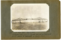
Unnumbered Image (5" x 7"): "1050' Cooper River Span - July 2, 1929. Suspended span swung as a simple span and jacking chords at U17 removed for replacement by dummy chords.";One 5" x 7" B/W photo
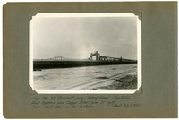
Unnumbered Image (5" x 7"): "From the Mt. Pleasant shore, looking toward Charleston, East Approach and Cooper River Span at right. Town Creek Span in the distance. (About July 2, 1929).";One 5" x 7" B/W photo
Image #510 (2.75" x 4.5"): "6-30-29. The completed Cooper River Span. Travelers and falsework not yet removed."; Image #511 (2.75" x 4.5"): "7-2-29. Removing the temporary jacking chords at U17."; Image #512 (2.75" x 4.5"): "7-1-29. The jacking chords at U17 removed."; Image #513 (2.75" x 4.5"): "7-2-29. The suspended span hanging free. Jacking chords at U17 removed.";Four 4.5" x 2.75" B/W photos numbered 510, 511, 512, 513